Yamaha CS1D Owner's Manual - Page 19
Control input/output connections, Power supply connections, Word clock connections
 |
View all Yamaha CS1D manuals
Add to My Manuals
Save this manual to your list of manuals |
Page 19 highlights
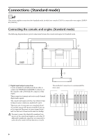
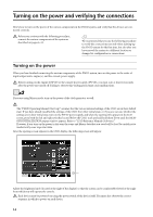
Connections (Mirror mode) Hint If both digital input/output connectors 1 and 2 are connected, connector 1 will be given priority when the power is turned on. If the word clock stops being supplied from either connector 1 or 2 (whichever is the currently-used connector), the receiving device will automatically switch to the other connector. 2 Control input/output connections Use BNC cables (50Ω) to connect the CONTROL I/ O ENGINE A IN and OUT connectors of the console to the CONTROL I/O OUT and IN connectors of engine A. In the same way, connect the CONTROL I/ O ENGINE B IN and OUT connectors of the console to the CONTROL I/O OUT and IN connectors of engine B. These connectors transmit and receive control signals between the console and engines A/B. The console and engines A/B each have two identical sets of connectors, numbered 1 and 2. These two sets of connectors are completely identical, and the system will operate normally if just one set is connected. However, you may connect both 1 and 2 so that one of them can be used as a backup. This method of connection is recommended for most cases. 22 22 22 22 MIDI IN OUT THRU CONTROL I/O CONSOLE 1 IN OUT 2 IN PC CONTROL RS-232-C OUT REMOTE RS-422 USB GPI WORD CLOCK IN CONSOLE CONTROL I/O ENGINE B ENGINE A 1 IN 1 IN 1 IN OUT 2 IN OUT 2 IN OUT 2 IN OUT OUT OUT Console (CS1D) MIDI IN OUT THRU CONTROL I/O CONSOLE 1 IN OUT 2 IN PC CONTROL RS-232-C OUT REMOTE RS-422 USB GPI WORD CLOCK IN 75Ω OFF ON OUT TIME CODE IN 75Ω OFF ON OUT TIME CODE IN Engine B Engine A Hint If both control input/output connectors 1 and 2 are connected, connector 1 will be given priority when the power is turned on. Control output connectors 1/2 will always output the same signals. If the currently-used control output connector stops functioning correctly, the receiving device will automatically switch to the other connector. You must connect the identically-numbered connectors of the console and engine to each other. If differently-numbered connectors are connected to each other, the system will not function correctly. 3 Power supply connections Use the included special cable to connect the DC POWER INPUT connector of the console to the DC OUTPUT connector of the PW1D power supply. The rear panel of the console has two DC POWER INPUT connectors, A and B. If you are using only one power supply, you may connect it to either DC POWER INPUT connector. You can also connect two power supplies to the two DC POWER INPUT connectors A and B. If this connection method is used, the PM1D system will continue to operate even if one of the power supplies should unexpectedly fail, since the other power supply will continue to supply power to the system. 4 Word clock connections Use BNC cables (75Ω) to connect the clock output connector of an external clock generator to the WORD CLOCK IN connector of the console, and to the WORD CLOCK IN connectors of engines A/B. Connect the word clock transmitting and receiving devices in a one-to-one relationship, and turn on the 75 Ω screen for the receiving device. The word clock transmission/reception circuit is designed with one-to-one connection in mind. For this reason, if you connect multiple receiving devices to a single clock transmission connector, performance may be impaired and the system may fail to operate correctly. If you cannot avoid using this type of connection, turn on the 75 Ω switch for one of the receiving devices, and turn off the 75 Ω switches for all remaining devices. In Mirror mode, you can also switch to the other engine manually if the currently-used engine experiences difficulties. In order to minimize the clock switching time in such cases, we recommend that you supply a word clock from an external clock generator to the console and to engines A/B. Of course, switching will occur even without this type of supply method. 11
-
 1
1 -
2
-
3
-
4
-
5
-
6
-
7
-
8
-
9
-
10
-
11
-
12
-
13
-
 14
14 -
 15
15 -
 16
16 -
 17
17 -
 18
18 -
 19
19 -
 20
20 -
 21
21 -
 22
22 -
 23
23 -
 24
24 -
25
-
26
-
27
-
28
-
29
-
30
-
31
-
32
-
33
-
34
-
35
-
36
-
37
-
38
-
39
-
40
-
41
-
42
-
43
-
44
-
45
-
46
-
47
-
48
-
49
-
50
-
51
-
52
-
53
-
54
-
55
-
56
-
57
-
58
-
59
-
60
-
61
-
62
-
63
-
64
-
65
-
66
-
67
-
68
-
69
-
70
-
71
-
72
-
73
-
74
-
75
-
76
-
77
-
78
-
79
-
80
-
81
-
82
-
83
-
84
-
85
-
86
-
87
-
88
-
89
-
90
-
91
-
92
-
93
-
94
-
95
-
96
-
97
-
98
-
99
-
100
-
101
-
102
-
103
-
104
-
105
-
106
-
107
-
108
-
109
-
110
-
111
-
112
-
113
-
114
-
115
-
116
-
117
-
118
-
119
-
120
-
121
-
122
-
123
-
124
-
125
-
126
-
127
-
128
-
129
-
130
-
131
-
132
-
133
-
134
-
135
-
136
-
137
-
138
-
139
-
140
-
141
-
142
-
143
-
144
-
145
-
146
-
147
-
148
-
149
-
150
-
151
-
152
-
153
-
154
-
155
-
156
-
157
-
158
-
159
-
160
-
161
-
162
-
163
-
164
-
165
-
166
-
167
-
168
-
169
-
170
-
171
-
172
-
173
-
174
-
175
-
176
-
177
-
178
-
179
-
180
-
181
-
182
-
183
-
184
-
185
-
186
-
187
-
188
-
189
-
190
-
191
-
192
-
193
-
194
-
195
-
196
-
197
-
198
-
199
-
200
-
201
-
202
-
203
-
204
-
205
-
206
-
207
-
208
-
209
-
210
-
211
-
212
-
213
-
214
-
215
-
216
-
217
-
218
-
219
-
220
-
221
-
222
-
223
-
224
-
225
-
226
-
227
-
228
-
229
-
230
-
231
-
232
-
233
-
234
-
235
-
236
-
237
-
238
-
239
-
240
-
241
-
242
-
243
-
244
-
245
-
246
-
247
-
248
-
249
-
250
-
251
-
252
-
253
-
254
-
255
-
256
-
257
-
258
-
259
-
260
-
261
-
262
-
263
-
264
-
265
-
266
-
267
-
268
-
269
-
270
-
271
-
272
-
273
-
274
-
275
-
276
-
277
-
278
-
279
-
280
-
281
-
282
-
283
-
284
-
285
-
286
-
287
-
288
-
289
-
290
-
291
-
292
-
293
-
294
-
295
-
296
-
297
-
298
-
299
-
300
-
301
-
302
-
303
-
304
-
305
-
306
-
307
-
308
-
309
-
310
-
311
-
312
-
313
-
314
-
315
-
316
-
317
-
318
-
319
-
320
-
321
-
322
-
323
-
324
-
325
-
326
-
327
-
328
-
329
-
330
-
331
-
332
-
333
-
334
-
335
-
336
-
337
-
338
-
339
-
340
-
341
-
342
-
343
-
344
-
345
-
346
-
347
-
348
-
349
-
350
-
351
-
352
-
353
-
354
-
355
-
356
-
357
-
358
-
359
-
360
-
361
-
362
-
363
-
364
-
365
-
366
-
367
-
368
-
369
-
370
-
371
-
372
-
373
-
374
-
375
-
376
-
377
-
378
-
379
-
380
-
381
-
382
-
383
-
384
-
385
-
386
-
387
-
388
-
389
-
390
-
391
-
392
-
393
-
394
-
395
-
396
-
397
-
398
-
399
-
400
-
401
-
402
-
403
-
404
-
405
-
406
-
407
-
408
-
409
-
410
-
411
-
412
-
413
-
414
-
415
-
416
-
417
-
418
-
419
-
420
-
421
-
422
-
423
-
424
-
425
-
426
-
427
-
428
-
429
-
430
-
431
-
432
-
433
-
434
-
435
-
436
-
437
-
438
-
439
-
440
-
441
-
442
-
443
-
444
-
445
-
446
-
447
-
448
-
449
-
450
-
451
-
452
-
453
-
454
-
455
-
456
-
457
-
458
-
459
-
460
-
461
-
462
-
463
-
464
-
465
-
466
-
467
-
468
-
469
-
470
-
471
-
472
-
473
-
474
-
475
-
476
-
477
-
478
-
479
-
480
-
481
-
482
-
483
-
484
-
485
-
486
-
487
-
488
-
489
-
490
-
491
-
492
-
493
-
494
-
495
-
496
-
497
-
498
-
499
-
500
-
501
-
502
-
503
-
504
-
505
-
506
-
507
-
508
-
509
-
510
-
511
-
512
-
513
-
514
-
515
-
516
-
517
-
518
-
519
-
520
-
521
-
522
-
523
-
524
-
525
-
526
-
527
-
528
-
529
-
530
-
531
-
532
-
533
-
534
-
535
-
536
-
537
-
538
-
539
-
540
-
541
-
542
-
543
-
544
-
545
-
546
-
547
-
548
-
549
-
550
-
551
-
552
-
553
-
554
-
555
-
556
-
557
-
558
-
559
-
560
-
561
-
562
-
563
-
564
-
565
-
566
-
567
-
568
-
569
-
570
-
571
-
572
-
573
-
574
-
575
-
576
-
577
-
578
-
579
-
580
-
581
-
582
-
583
-
584
-
585
-
586
-
587
-
588
-
589
-
590
-
591
-
592
-
593
-
594
-
595
-
596
-
597
-
598
-
599
-
600
-
601
-
602
-
603
-
604
-
605
-
606
-
607
-
608
-
609
-
610
-
611
-
612
-
613
-
614
-
615
-
616
-
617
 |
 |
