Yamaha CS1D Owner's Manual - Page 245
NOISE GATE [ON] switch and LED
 |
View all Yamaha CS1D manuals
Add to My Manuals
Save this manual to your list of manuals |
Page 245 highlights
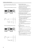
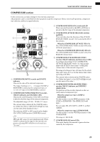
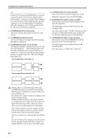
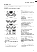
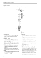
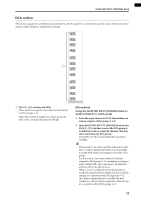
CS1D Reference Manual (Hardware) The current value is shown by the [VALUE] indicator. (Either the [msec] or [sec] LED will light to indicate the units of the displayed value.) 9 NOISE GATE [GR] meter LEDs This meter shows how far the noise gate has closed. Hint In the UTILITY function PREFERENCE screen you can specify whether the GR meter display will be linked with the noise gate on/off setting. If linking is on, the GR meter will be displayed only when the noise gate is on; the meter will not be displayed when the noise gate is off. If linking is turned off, the GR meter will always be displayed. 0 NOISE GATE [POST] meter LEDs This meter indicates the signal level after passing through the noise gate. A NOISE GATE [LINK] switch and LED This specifies whether noise gate operation of adjacent odd-numbered → even-numbered input channels will be linked by a key-in signal (link=on) or whether the noise gate will operate using independent key-in signals (link=off). (The LED will light when link is on.) • Key-in signal flow when link=on LINK = ON Key-in signal of odd- THR numbered channel Detect the ATTACK processing GR maximum Key-in signal of even- THR level numbered channel ATTACK processing GR • Key-in signal flow when link=off LINK = OFF Key-in signal of odd- THR Detect the numbered channel maximum level ATTACK processing GR Key-in signal of even- THR Detect the numbered channel maximum level ATTACK processing GR Linking will occur only if channels of the same NOISE GATE type are linked. If channels with differing types are linked, the operation will be the same as if link is off. Be careful not to confuse "noise gate linking" with "input channel pairing." Turning noise gate link on will simply cause the two noise gates to be triggered by the same key-in signal; the parameters of the noise gates themselves can be set independently for each channel. If two input channels are paired, noise gate link will automatically be turned on, and the noise gate parameters will also operate in tandem. However, you are free to subsequently turn linking off. For a ST IN channel, the noise gate parameters for the left and right channels will always operate in tandem. However, you are free to turn link on/off. B NOISE GATE [ON] switch and LED This switch turns the internal noise gate on/off. When the noise gate is on, the switch LED will light. C NOISE GATE [RANGE] encoder and LEDs This encoder sets the RANGE parameter of the internal noise gate. The approximate current value is shown by the perimeter LEDs. The range is -70 dB-0 dB (1 dB units). D NOISE GATE [THR] encoder and LEDs This encoder sets the THRESHOLD parameter of the internal noise gate. The approximate current value is shown by the perimeter LEDs. The range is -54 dB-0 dB (1 dB units). 28
-
 1
1 -
2
-
3
-
4
-
5
-
6
-
7
-
8
-
9
-
10
-
11
-
12
-
13
-
14
-
15
-
16
-
17
-
18
-
19
-
20
-
21
-
22
-
23
-
24
-
25
-
26
-
27
-
28
-
29
-
30
-
31
-
32
-
33
-
34
-
35
-
36
-
37
-
38
-
39
-
40
-
41
-
42
-
43
-
44
-
45
-
46
-
47
-
48
-
49
-
50
-
51
-
52
-
53
-
54
-
55
-
56
-
57
-
58
-
59
-
60
-
61
-
62
-
63
-
64
-
65
-
66
-
67
-
68
-
69
-
70
-
71
-
72
-
73
-
74
-
75
-
76
-
77
-
78
-
79
-
80
-
81
-
82
-
83
-
84
-
85
-
86
-
87
-
88
-
89
-
90
-
91
-
92
-
93
-
94
-
95
-
96
-
97
-
98
-
99
-
100
-
101
-
102
-
103
-
104
-
105
-
106
-
107
-
108
-
109
-
110
-
111
-
112
-
113
-
114
-
115
-
116
-
117
-
118
-
119
-
120
-
121
-
122
-
123
-
124
-
125
-
126
-
127
-
128
-
129
-
130
-
131
-
132
-
133
-
134
-
135
-
136
-
137
-
138
-
139
-
140
-
141
-
142
-
143
-
144
-
145
-
146
-
147
-
148
-
149
-
150
-
151
-
152
-
153
-
154
-
155
-
156
-
157
-
158
-
159
-
160
-
161
-
162
-
163
-
164
-
165
-
166
-
167
-
168
-
169
-
170
-
171
-
172
-
173
-
174
-
175
-
176
-
177
-
178
-
179
-
180
-
181
-
182
-
183
-
184
-
185
-
186
-
187
-
188
-
189
-
190
-
191
-
192
-
193
-
194
-
195
-
196
-
197
-
198
-
199
-
200
-
201
-
202
-
203
-
204
-
205
-
206
-
207
-
208
-
209
-
210
-
211
-
212
-
213
-
214
-
215
-
216
-
217
-
218
-
219
-
220
-
221
-
222
-
223
-
224
-
225
-
226
-
227
-
228
-
229
-
230
-
231
-
232
-
233
-
234
-
235
-
236
-
237
-
238
-
239
-
 240
240 -
 241
241 -
 242
242 -
 243
243 -
 244
244 -
 245
245 -
 246
246 -
 247
247 -
 248
248 -
 249
249 -
 250
250 -
251
-
252
-
253
-
254
-
255
-
256
-
257
-
258
-
259
-
260
-
261
-
262
-
263
-
264
-
265
-
266
-
267
-
268
-
269
-
270
-
271
-
272
-
273
-
274
-
275
-
276
-
277
-
278
-
279
-
280
-
281
-
282
-
283
-
284
-
285
-
286
-
287
-
288
-
289
-
290
-
291
-
292
-
293
-
294
-
295
-
296
-
297
-
298
-
299
-
300
-
301
-
302
-
303
-
304
-
305
-
306
-
307
-
308
-
309
-
310
-
311
-
312
-
313
-
314
-
315
-
316
-
317
-
318
-
319
-
320
-
321
-
322
-
323
-
324
-
325
-
326
-
327
-
328
-
329
-
330
-
331
-
332
-
333
-
334
-
335
-
336
-
337
-
338
-
339
-
340
-
341
-
342
-
343
-
344
-
345
-
346
-
347
-
348
-
349
-
350
-
351
-
352
-
353
-
354
-
355
-
356
-
357
-
358
-
359
-
360
-
361
-
362
-
363
-
364
-
365
-
366
-
367
-
368
-
369
-
370
-
371
-
372
-
373
-
374
-
375
-
376
-
377
-
378
-
379
-
380
-
381
-
382
-
383
-
384
-
385
-
386
-
387
-
388
-
389
-
390
-
391
-
392
-
393
-
394
-
395
-
396
-
397
-
398
-
399
-
400
-
401
-
402
-
403
-
404
-
405
-
406
-
407
-
408
-
409
-
410
-
411
-
412
-
413
-
414
-
415
-
416
-
417
-
418
-
419
-
420
-
421
-
422
-
423
-
424
-
425
-
426
-
427
-
428
-
429
-
430
-
431
-
432
-
433
-
434
-
435
-
436
-
437
-
438
-
439
-
440
-
441
-
442
-
443
-
444
-
445
-
446
-
447
-
448
-
449
-
450
-
451
-
452
-
453
-
454
-
455
-
456
-
457
-
458
-
459
-
460
-
461
-
462
-
463
-
464
-
465
-
466
-
467
-
468
-
469
-
470
-
471
-
472
-
473
-
474
-
475
-
476
-
477
-
478
-
479
-
480
-
481
-
482
-
483
-
484
-
485
-
486
-
487
-
488
-
489
-
490
-
491
-
492
-
493
-
494
-
495
-
496
-
497
-
498
-
499
-
500
-
501
-
502
-
503
-
504
-
505
-
506
-
507
-
508
-
509
-
510
-
511
-
512
-
513
-
514
-
515
-
516
-
517
-
518
-
519
-
520
-
521
-
522
-
523
-
524
-
525
-
526
-
527
-
528
-
529
-
530
-
531
-
532
-
533
-
534
-
535
-
536
-
537
-
538
-
539
-
540
-
541
-
542
-
543
-
544
-
545
-
546
-
547
-
548
-
549
-
550
-
551
-
552
-
553
-
554
-
555
-
556
-
557
-
558
-
559
-
560
-
561
-
562
-
563
-
564
-
565
-
566
-
567
-
568
-
569
-
570
-
571
-
572
-
573
-
574
-
575
-
576
-
577
-
578
-
579
-
580
-
581
-
582
-
583
-
584
-
585
-
586
-
587
-
588
-
589
-
590
-
591
-
592
-
593
-
594
-
595
-
596
-
597
-
598
-
599
-
600
-
601
-
602
-
603
-
604
-
605
-
606
-
607
-
608
-
609
-
610
-
611
-
612
-
613
-
614
-
615
-
616
-
617
 |
 |
