Yamaha CS1D Owner's Manual - Page 277
COMPRESSOR When the COMPRESSOR [ATTACK] LED is lit
 |
View all Yamaha CS1D manuals
Add to My Manuals
Save this manual to your list of manuals |
Page 277 highlights
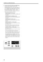
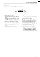
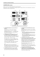
CS1D Reference Manual (Hardware) COMPRESSOR section In this section you can make settings for the internal compressor. All parameters can be controlled from the top panel except for compressor library store/recall operations, compressor type selection, and key-in signal selection. 1 3 2 5 4 0 6 7 A 8 B C 9 COMPRESSOR 1 COMPRESSOR [RATIO] encoder and [VALUE] indicator This sets the ratio of the internal compressor. When the compressor type is set to COMP or EXPANDER, the range is 1:1- ∞:1 (16 steps). When the compressor type is set to COMPANDER, the range is 1:1-20:1 (15 steps). 2 COMPRESSOR FILTER [FREQUENCY] encoder and [VALUE] indicator and [Hz]/[kHz] LEDs This sets the cutoff frequency of the HPF or LPF that is placed in the first stage of the internal compressor. The range is 20 Hz - 20 kHz (121 steps). The current value is shown in the [VALUE] indicator. (Either the [Hz] or [kHz] LED will light to indicate the units of the displayed value.) The selection of HPF or LPF is made in the display (OUT COMP function COMP PRM screen). Hint HPF and LPF cannot be used simultaneously. If COMP is selected as the internal compressor type, selecting HPF will allow it to function as a "de-esser." 3 COMPRESSOR FILTER [ON] switch and LED This is an on/off switch for the HPF or LPF that is placed in the first stage of the internal compressor. 4 COMPRESSOR [ATTACK]/[RELEASE] switches and LEDs These switches select the function of the ATTACK/ RELEASE [TIME] encoder (5) located to the left of the switches. • When the COMPRESSOR [ATTACK] LED is lit, the ATTACK/RELEASE [TIME] encoder will set the ATTACK (attack time) • When the COMPRESSOR [RELEASE] LED is lit, the ATTACK/RELEASE [TIME] encoder will set the RELEASE (release time) 5 COMPRESSOR ATTACK/RELEASE [TIME] encoder, [VALUE] indicator, and [msec]/[sec] LEDs This encoder adjusts the ATTACK (attack time) or RELEASE (release time) of the internal compressor, according to the setting of the COMPRESSOR [ATTACK]/[RELEASE] switches (4). The attack time range is 0 msec - 120 msec . The release time range is 5 msec - 42.3 sec. The current value is shown in the [VALUE] indicator. (Either the [msec] or [sec] LED will light to indicate the units of the displayed value.) 6 COMPRESSOR WIDTH (dB)/KNEE encoder, [VALUE] indicator, and [WIDTH]/[KNEE] LEDs The function of this encoder will depend on the currently selected compressor type. 60
-
 1
1 -
2
-
3
-
4
-
5
-
6
-
7
-
8
-
9
-
10
-
11
-
12
-
13
-
14
-
15
-
16
-
17
-
18
-
19
-
20
-
21
-
22
-
23
-
24
-
25
-
26
-
27
-
28
-
29
-
30
-
31
-
32
-
33
-
34
-
35
-
36
-
37
-
38
-
39
-
40
-
41
-
42
-
43
-
44
-
45
-
46
-
47
-
48
-
49
-
50
-
51
-
52
-
53
-
54
-
55
-
56
-
57
-
58
-
59
-
60
-
61
-
62
-
63
-
64
-
65
-
66
-
67
-
68
-
69
-
70
-
71
-
72
-
73
-
74
-
75
-
76
-
77
-
78
-
79
-
80
-
81
-
82
-
83
-
84
-
85
-
86
-
87
-
88
-
89
-
90
-
91
-
92
-
93
-
94
-
95
-
96
-
97
-
98
-
99
-
100
-
101
-
102
-
103
-
104
-
105
-
106
-
107
-
108
-
109
-
110
-
111
-
112
-
113
-
114
-
115
-
116
-
117
-
118
-
119
-
120
-
121
-
122
-
123
-
124
-
125
-
126
-
127
-
128
-
129
-
130
-
131
-
132
-
133
-
134
-
135
-
136
-
137
-
138
-
139
-
140
-
141
-
142
-
143
-
144
-
145
-
146
-
147
-
148
-
149
-
150
-
151
-
152
-
153
-
154
-
155
-
156
-
157
-
158
-
159
-
160
-
161
-
162
-
163
-
164
-
165
-
166
-
167
-
168
-
169
-
170
-
171
-
172
-
173
-
174
-
175
-
176
-
177
-
178
-
179
-
180
-
181
-
182
-
183
-
184
-
185
-
186
-
187
-
188
-
189
-
190
-
191
-
192
-
193
-
194
-
195
-
196
-
197
-
198
-
199
-
200
-
201
-
202
-
203
-
204
-
205
-
206
-
207
-
208
-
209
-
210
-
211
-
212
-
213
-
214
-
215
-
216
-
217
-
218
-
219
-
220
-
221
-
222
-
223
-
224
-
225
-
226
-
227
-
228
-
229
-
230
-
231
-
232
-
233
-
234
-
235
-
236
-
237
-
238
-
239
-
240
-
241
-
242
-
243
-
244
-
245
-
246
-
247
-
248
-
249
-
250
-
251
-
252
-
253
-
254
-
255
-
256
-
257
-
258
-
259
-
260
-
261
-
262
-
263
-
264
-
265
-
266
-
267
-
268
-
269
-
270
-
271
-
 272
272 -
 273
273 -
 274
274 -
 275
275 -
 276
276 -
 277
277 -
 278
278 -
 279
279 -
 280
280 -
 281
281 -
 282
282 -
283
-
284
-
285
-
286
-
287
-
288
-
289
-
290
-
291
-
292
-
293
-
294
-
295
-
296
-
297
-
298
-
299
-
300
-
301
-
302
-
303
-
304
-
305
-
306
-
307
-
308
-
309
-
310
-
311
-
312
-
313
-
314
-
315
-
316
-
317
-
318
-
319
-
320
-
321
-
322
-
323
-
324
-
325
-
326
-
327
-
328
-
329
-
330
-
331
-
332
-
333
-
334
-
335
-
336
-
337
-
338
-
339
-
340
-
341
-
342
-
343
-
344
-
345
-
346
-
347
-
348
-
349
-
350
-
351
-
352
-
353
-
354
-
355
-
356
-
357
-
358
-
359
-
360
-
361
-
362
-
363
-
364
-
365
-
366
-
367
-
368
-
369
-
370
-
371
-
372
-
373
-
374
-
375
-
376
-
377
-
378
-
379
-
380
-
381
-
382
-
383
-
384
-
385
-
386
-
387
-
388
-
389
-
390
-
391
-
392
-
393
-
394
-
395
-
396
-
397
-
398
-
399
-
400
-
401
-
402
-
403
-
404
-
405
-
406
-
407
-
408
-
409
-
410
-
411
-
412
-
413
-
414
-
415
-
416
-
417
-
418
-
419
-
420
-
421
-
422
-
423
-
424
-
425
-
426
-
427
-
428
-
429
-
430
-
431
-
432
-
433
-
434
-
435
-
436
-
437
-
438
-
439
-
440
-
441
-
442
-
443
-
444
-
445
-
446
-
447
-
448
-
449
-
450
-
451
-
452
-
453
-
454
-
455
-
456
-
457
-
458
-
459
-
460
-
461
-
462
-
463
-
464
-
465
-
466
-
467
-
468
-
469
-
470
-
471
-
472
-
473
-
474
-
475
-
476
-
477
-
478
-
479
-
480
-
481
-
482
-
483
-
484
-
485
-
486
-
487
-
488
-
489
-
490
-
491
-
492
-
493
-
494
-
495
-
496
-
497
-
498
-
499
-
500
-
501
-
502
-
503
-
504
-
505
-
506
-
507
-
508
-
509
-
510
-
511
-
512
-
513
-
514
-
515
-
516
-
517
-
518
-
519
-
520
-
521
-
522
-
523
-
524
-
525
-
526
-
527
-
528
-
529
-
530
-
531
-
532
-
533
-
534
-
535
-
536
-
537
-
538
-
539
-
540
-
541
-
542
-
543
-
544
-
545
-
546
-
547
-
548
-
549
-
550
-
551
-
552
-
553
-
554
-
555
-
556
-
557
-
558
-
559
-
560
-
561
-
562
-
563
-
564
-
565
-
566
-
567
-
568
-
569
-
570
-
571
-
572
-
573
-
574
-
575
-
576
-
577
-
578
-
579
-
580
-
581
-
582
-
583
-
584
-
585
-
586
-
587
-
588
-
589
-
590
-
591
-
592
-
593
-
594
-
595
-
596
-
597
-
598
-
599
-
600
-
601
-
602
-
603
-
604
-
605
-
606
-
607
-
608
-
609
-
610
-
611
-
612
-
613
-
614
-
615
-
616
-
617
 |
 |
