Yamaha CS1D Owner's Manual - Page 244
Noise Gate Noise Gate Key In Filter [on] Switch
 |
View all Yamaha CS1D manuals
Add to My Manuals
Save this manual to your list of manuals |
Page 244 highlights
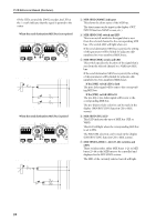
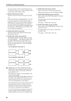
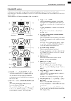
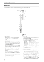
SELECTED INPUT CHANNEL block NOISE GATE section In this section you can make settings for the internal noise gate. All parameters can be controlled from the top panel, except for noise gate library store/recall operations, noise gate type selection, and key-in signal selection. 1 2 3 4 5 7 6 A 8 9 0 B C D NOISE GATE 1 NOISE GATE KEY IN FILTER [HPF]/[LPF] switch Of the two filters (HPF and LPF) provided for the key-in signal of the noise gate, this switch selects the filter that you wish to adjust. The LED of the currently selected switch will light. Hint You can simultaneously use both the HPF and LPF. The HPF and LPF are applied only to the key-in signal sent to the noise gate. They do not affect the signals that are sent to the STEREO bus or the MIX buses. 2 NOISE GATE KEY IN FILTER [FREQUENCY] encoder, [VALUE] indicator, and [Hz]/[kHz] LEDs This encoder sets the cutoff frequency of the filter (LPF or HPF) selected by the KEY IN FILTER [HPF]/ [LPF] switch (1). The range of frequency adjustment is 20 Hz-20 kHz (121 steps). The current value is shown in the [VALUE] indicator. (Either the [Hz] or [kHz] indicator will light to indicate the units of the displayed value.) 3 NOISE GATE KEY IN FILTER [ON] switch and LED This is an on/off switch for the filter selected (LPF or HPF) selected by the KEY IN FILTER [HPF]/[LPF] switch (1). When this is on, the switch LED will light. 4 NOISE GATE SIG [+]/[THR]/[-] LEDs These LEDs indicate the level of the noise gate key-in signal (after passing through the filters). At the threshold level, [THR] will light. When the key-in signal exceeds the threshold level [+] will light, and when it is below the threshold level [-] will light. 5 NOISE GATE KEY IN [CUE] switch and LED This switch allows you to monitor the noise gate keyin signal. When this switch is pressed, the noise gate key-in signal (after passing through the filters) of the currently selected channel will be sent to the CUE bus, and can be monitored via the CUE OUT jacks, MONITOR OUT jacks A, and PHONES jack. The LED will light while this is being monitored. While this switch is on, all three of the CUE ACTIVE LEDs in the CUE section of the MASTER block will light. 6 NOISE GATE [ATTACK]/[DECAY] switches and LEDs These switches select the function of the NOISE GATE ATTACK/DECAY [TIME] encoder (7) located at the left of the switches. When the NOISE GATE [ATTACK] LED is lit, the encoder will set the ATTACK (attack time). When the NOISE GATE [DECAY] LED is lit, the encoder will set the DECAY (decay time). 7 NOISE GATE ATTACK/DECAY [TIME] encoder, [VALUE] indicator, and [msec]/[sec] LEDs Depending on the setting of the NOISE GATE [ATTACK]/[DECAY] switch (6), this encoder adjusts either the ATTACK (attack time) or the DECAY (decay time) of the internal noise gate. The range for the attack time is 0 msec-120 msec, and for the decay time is 5 msec-42.3 sec (when operating at 48 kHz). The current value is shown by the [VALUE] indicator. (Either the [msec] or [sec] LED will light to indicate the units of the displayed value.) 8 NOISE GATE HOLD [TIME] encoder, [VALUE] indicator, and [msec]/[sec] LEDs These set and display the hold time of the internal noise gate. The range is 0.02 msec-1.96 sec (when operating at 48 kHz). 27
-
 1
1 -
2
-
3
-
4
-
5
-
6
-
7
-
8
-
9
-
10
-
11
-
12
-
13
-
14
-
15
-
16
-
17
-
18
-
19
-
20
-
21
-
22
-
23
-
24
-
25
-
26
-
27
-
28
-
29
-
30
-
31
-
32
-
33
-
34
-
35
-
36
-
37
-
38
-
39
-
40
-
41
-
42
-
43
-
44
-
45
-
46
-
47
-
48
-
49
-
50
-
51
-
52
-
53
-
54
-
55
-
56
-
57
-
58
-
59
-
60
-
61
-
62
-
63
-
64
-
65
-
66
-
67
-
68
-
69
-
70
-
71
-
72
-
73
-
74
-
75
-
76
-
77
-
78
-
79
-
80
-
81
-
82
-
83
-
84
-
85
-
86
-
87
-
88
-
89
-
90
-
91
-
92
-
93
-
94
-
95
-
96
-
97
-
98
-
99
-
100
-
101
-
102
-
103
-
104
-
105
-
106
-
107
-
108
-
109
-
110
-
111
-
112
-
113
-
114
-
115
-
116
-
117
-
118
-
119
-
120
-
121
-
122
-
123
-
124
-
125
-
126
-
127
-
128
-
129
-
130
-
131
-
132
-
133
-
134
-
135
-
136
-
137
-
138
-
139
-
140
-
141
-
142
-
143
-
144
-
145
-
146
-
147
-
148
-
149
-
150
-
151
-
152
-
153
-
154
-
155
-
156
-
157
-
158
-
159
-
160
-
161
-
162
-
163
-
164
-
165
-
166
-
167
-
168
-
169
-
170
-
171
-
172
-
173
-
174
-
175
-
176
-
177
-
178
-
179
-
180
-
181
-
182
-
183
-
184
-
185
-
186
-
187
-
188
-
189
-
190
-
191
-
192
-
193
-
194
-
195
-
196
-
197
-
198
-
199
-
200
-
201
-
202
-
203
-
204
-
205
-
206
-
207
-
208
-
209
-
210
-
211
-
212
-
213
-
214
-
215
-
216
-
217
-
218
-
219
-
220
-
221
-
222
-
223
-
224
-
225
-
226
-
227
-
228
-
229
-
230
-
231
-
232
-
233
-
234
-
235
-
236
-
237
-
238
-
 239
239 -
 240
240 -
 241
241 -
 242
242 -
 243
243 -
 244
244 -
 245
245 -
 246
246 -
 247
247 -
 248
248 -
 249
249 -
250
-
251
-
252
-
253
-
254
-
255
-
256
-
257
-
258
-
259
-
260
-
261
-
262
-
263
-
264
-
265
-
266
-
267
-
268
-
269
-
270
-
271
-
272
-
273
-
274
-
275
-
276
-
277
-
278
-
279
-
280
-
281
-
282
-
283
-
284
-
285
-
286
-
287
-
288
-
289
-
290
-
291
-
292
-
293
-
294
-
295
-
296
-
297
-
298
-
299
-
300
-
301
-
302
-
303
-
304
-
305
-
306
-
307
-
308
-
309
-
310
-
311
-
312
-
313
-
314
-
315
-
316
-
317
-
318
-
319
-
320
-
321
-
322
-
323
-
324
-
325
-
326
-
327
-
328
-
329
-
330
-
331
-
332
-
333
-
334
-
335
-
336
-
337
-
338
-
339
-
340
-
341
-
342
-
343
-
344
-
345
-
346
-
347
-
348
-
349
-
350
-
351
-
352
-
353
-
354
-
355
-
356
-
357
-
358
-
359
-
360
-
361
-
362
-
363
-
364
-
365
-
366
-
367
-
368
-
369
-
370
-
371
-
372
-
373
-
374
-
375
-
376
-
377
-
378
-
379
-
380
-
381
-
382
-
383
-
384
-
385
-
386
-
387
-
388
-
389
-
390
-
391
-
392
-
393
-
394
-
395
-
396
-
397
-
398
-
399
-
400
-
401
-
402
-
403
-
404
-
405
-
406
-
407
-
408
-
409
-
410
-
411
-
412
-
413
-
414
-
415
-
416
-
417
-
418
-
419
-
420
-
421
-
422
-
423
-
424
-
425
-
426
-
427
-
428
-
429
-
430
-
431
-
432
-
433
-
434
-
435
-
436
-
437
-
438
-
439
-
440
-
441
-
442
-
443
-
444
-
445
-
446
-
447
-
448
-
449
-
450
-
451
-
452
-
453
-
454
-
455
-
456
-
457
-
458
-
459
-
460
-
461
-
462
-
463
-
464
-
465
-
466
-
467
-
468
-
469
-
470
-
471
-
472
-
473
-
474
-
475
-
476
-
477
-
478
-
479
-
480
-
481
-
482
-
483
-
484
-
485
-
486
-
487
-
488
-
489
-
490
-
491
-
492
-
493
-
494
-
495
-
496
-
497
-
498
-
499
-
500
-
501
-
502
-
503
-
504
-
505
-
506
-
507
-
508
-
509
-
510
-
511
-
512
-
513
-
514
-
515
-
516
-
517
-
518
-
519
-
520
-
521
-
522
-
523
-
524
-
525
-
526
-
527
-
528
-
529
-
530
-
531
-
532
-
533
-
534
-
535
-
536
-
537
-
538
-
539
-
540
-
541
-
542
-
543
-
544
-
545
-
546
-
547
-
548
-
549
-
550
-
551
-
552
-
553
-
554
-
555
-
556
-
557
-
558
-
559
-
560
-
561
-
562
-
563
-
564
-
565
-
566
-
567
-
568
-
569
-
570
-
571
-
572
-
573
-
574
-
575
-
576
-
577
-
578
-
579
-
580
-
581
-
582
-
583
-
584
-
585
-
586
-
587
-
588
-
589
-
590
-
591
-
592
-
593
-
594
-
595
-
596
-
597
-
598
-
599
-
600
-
601
-
602
-
603
-
604
-
605
-
606
-
607
-
608
-
609
-
610
-
611
-
612
-
613
-
614
-
615
-
616
-
617
 |
 |
