Yamaha CS1D Owner's Manual - Page 278
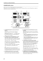
COMPRESSOR [GAIN] encoder and LEDs, COMPRESSOR [LINK] switch and LED
 |
View all Yamaha CS1D manuals
Add to My Manuals
Save this manual to your list of manuals |
Page 278 highlights
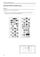
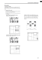
• When the compressor type is COMP or EXPANDER The encoder will set the KNEE parameter of the COMP or EXPANDER. (The [KNEE] LED will light.) You can select from SOFT 1-SOFT 5, or HARD. • When the compressor type is COMPANDER The encoder will set the WIDTH parameter of the COMPANDER. The range is 1 dB - 90 dB. 7 COMPRESSOR [GR] meter LEDs This meter displays the amount of gain reduction caused by the compressor. Hint In the UTILITY function PREFERENCE screen you can specify whether the GR meter display will be linked with the compressor on/off setting. If linking is on, the GR meter will be displayed only when the compressor is on; the meter will not be displayed when the compressor is off. If linking is turned off, the GR meter will always be displayed. 8 COMPRESSOR [POST] meter LEDs This meter indicates the signal level after the compressor. 9 COMPRESSOR [PRE CLIP] LED This LED will light when the signal has clipped before passing through the compressor. 0 COMPRESSOR [LINK] switch and LED This specifies whether the compressors of adjacent odd-numbered and even-numbered MIX channels or MATRIX channels will be linked by their key-in signals (link = on), or will operate using independent key-in signals (link = off). (The LED will light when link is on.) • Key-in signal flow when link=on LINK = ON Key-in signal of odd- THR numbered channel Detect the ATTACK processing GR maximum Key-in signal of even- THR level numbered channel ATTACK processing GR • Key-in signal flow when link=off LINK = OFF Key-in signal of odd- THR Detect the numbered channel maximum level ATTACK processing GR Key-in signal of even- THR Detect the numbered channel maximum level ATTACK processing GR Linking will occur only if channels of the same COMPRESSOR type are linked. If channels with differing types are linked, the operation will be the same as if link is off. Be careful not to confuse "compressor linking" with "input channel pairing." SELECTED OUTPUT CHANNEL block When compressor link is on, the compressor operation will simply be linked by the key-in signal; the compressor parameters themselves will remain independent for each channel. If output channels are paired, compressor link will automatically be on, and the various compressor parameters will also be linked. However, you are free to turn linking off again if desired. For the STEREO A/B channels, the compressor parameters of the left and right channels are always linked. However, you are free to turn link on/off if you wish. A COMPRESSOR [ON] switch and LED This is the on/off switch for the internal compressor. The LED will light when the compressor is on. B COMPRESSOR [GAIN] encoder and LEDs This encoder sets the GAIN parameter of the internal compressor. The perimeter LEDs show the approximate current value. When the type is COMP/EXPANDER, the range is 0 dB - +18 dB (0.5 dB steps). When the type is COMPANDER, the range is -18 dB - 0 dB (0.5 dB steps). C COMPRESSOR [THR] encoder and LEDs This encoder sets the THRESHOLD LEVEL parameter of the internal compressor. The perimeter LEDs show the approximate current value. The range is -54 dB - 0 dB (1 dB steps). 61
-
 1
1 -
2
-
3
-
4
-
5
-
6
-
7
-
8
-
9
-
10
-
11
-
12
-
13
-
14
-
15
-
16
-
17
-
18
-
19
-
20
-
21
-
22
-
23
-
24
-
25
-
26
-
27
-
28
-
29
-
30
-
31
-
32
-
33
-
34
-
35
-
36
-
37
-
38
-
39
-
40
-
41
-
42
-
43
-
44
-
45
-
46
-
47
-
48
-
49
-
50
-
51
-
52
-
53
-
54
-
55
-
56
-
57
-
58
-
59
-
60
-
61
-
62
-
63
-
64
-
65
-
66
-
67
-
68
-
69
-
70
-
71
-
72
-
73
-
74
-
75
-
76
-
77
-
78
-
79
-
80
-
81
-
82
-
83
-
84
-
85
-
86
-
87
-
88
-
89
-
90
-
91
-
92
-
93
-
94
-
95
-
96
-
97
-
98
-
99
-
100
-
101
-
102
-
103
-
104
-
105
-
106
-
107
-
108
-
109
-
110
-
111
-
112
-
113
-
114
-
115
-
116
-
117
-
118
-
119
-
120
-
121
-
122
-
123
-
124
-
125
-
126
-
127
-
128
-
129
-
130
-
131
-
132
-
133
-
134
-
135
-
136
-
137
-
138
-
139
-
140
-
141
-
142
-
143
-
144
-
145
-
146
-
147
-
148
-
149
-
150
-
151
-
152
-
153
-
154
-
155
-
156
-
157
-
158
-
159
-
160
-
161
-
162
-
163
-
164
-
165
-
166
-
167
-
168
-
169
-
170
-
171
-
172
-
173
-
174
-
175
-
176
-
177
-
178
-
179
-
180
-
181
-
182
-
183
-
184
-
185
-
186
-
187
-
188
-
189
-
190
-
191
-
192
-
193
-
194
-
195
-
196
-
197
-
198
-
199
-
200
-
201
-
202
-
203
-
204
-
205
-
206
-
207
-
208
-
209
-
210
-
211
-
212
-
213
-
214
-
215
-
216
-
217
-
218
-
219
-
220
-
221
-
222
-
223
-
224
-
225
-
226
-
227
-
228
-
229
-
230
-
231
-
232
-
233
-
234
-
235
-
236
-
237
-
238
-
239
-
240
-
241
-
242
-
243
-
244
-
245
-
246
-
247
-
248
-
249
-
250
-
251
-
252
-
253
-
254
-
255
-
256
-
257
-
258
-
259
-
260
-
261
-
262
-
263
-
264
-
265
-
266
-
267
-
268
-
269
-
270
-
271
-
272
-
 273
273 -
 274
274 -
 275
275 -
 276
276 -
 277
277 -
 278
278 -
 279
279 -
 280
280 -
 281
281 -
 282
282 -
 283
283 -
284
-
285
-
286
-
287
-
288
-
289
-
290
-
291
-
292
-
293
-
294
-
295
-
296
-
297
-
298
-
299
-
300
-
301
-
302
-
303
-
304
-
305
-
306
-
307
-
308
-
309
-
310
-
311
-
312
-
313
-
314
-
315
-
316
-
317
-
318
-
319
-
320
-
321
-
322
-
323
-
324
-
325
-
326
-
327
-
328
-
329
-
330
-
331
-
332
-
333
-
334
-
335
-
336
-
337
-
338
-
339
-
340
-
341
-
342
-
343
-
344
-
345
-
346
-
347
-
348
-
349
-
350
-
351
-
352
-
353
-
354
-
355
-
356
-
357
-
358
-
359
-
360
-
361
-
362
-
363
-
364
-
365
-
366
-
367
-
368
-
369
-
370
-
371
-
372
-
373
-
374
-
375
-
376
-
377
-
378
-
379
-
380
-
381
-
382
-
383
-
384
-
385
-
386
-
387
-
388
-
389
-
390
-
391
-
392
-
393
-
394
-
395
-
396
-
397
-
398
-
399
-
400
-
401
-
402
-
403
-
404
-
405
-
406
-
407
-
408
-
409
-
410
-
411
-
412
-
413
-
414
-
415
-
416
-
417
-
418
-
419
-
420
-
421
-
422
-
423
-
424
-
425
-
426
-
427
-
428
-
429
-
430
-
431
-
432
-
433
-
434
-
435
-
436
-
437
-
438
-
439
-
440
-
441
-
442
-
443
-
444
-
445
-
446
-
447
-
448
-
449
-
450
-
451
-
452
-
453
-
454
-
455
-
456
-
457
-
458
-
459
-
460
-
461
-
462
-
463
-
464
-
465
-
466
-
467
-
468
-
469
-
470
-
471
-
472
-
473
-
474
-
475
-
476
-
477
-
478
-
479
-
480
-
481
-
482
-
483
-
484
-
485
-
486
-
487
-
488
-
489
-
490
-
491
-
492
-
493
-
494
-
495
-
496
-
497
-
498
-
499
-
500
-
501
-
502
-
503
-
504
-
505
-
506
-
507
-
508
-
509
-
510
-
511
-
512
-
513
-
514
-
515
-
516
-
517
-
518
-
519
-
520
-
521
-
522
-
523
-
524
-
525
-
526
-
527
-
528
-
529
-
530
-
531
-
532
-
533
-
534
-
535
-
536
-
537
-
538
-
539
-
540
-
541
-
542
-
543
-
544
-
545
-
546
-
547
-
548
-
549
-
550
-
551
-
552
-
553
-
554
-
555
-
556
-
557
-
558
-
559
-
560
-
561
-
562
-
563
-
564
-
565
-
566
-
567
-
568
-
569
-
570
-
571
-
572
-
573
-
574
-
575
-
576
-
577
-
578
-
579
-
580
-
581
-
582
-
583
-
584
-
585
-
586
-
587
-
588
-
589
-
590
-
591
-
592
-
593
-
594
-
595
-
596
-
597
-
598
-
599
-
600
-
601
-
602
-
603
-
604
-
605
-
606
-
607
-
608
-
609
-
610
-
611
-
612
-
613
-
614
-
615
-
616
-
617
 |
 |
