Cisco N7K-C7010 Configuration Guide
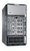
Cisco N7K-C7010 - Nexus 7000 Series Switch Manual
 |
UPC - 882658174445
View all Cisco N7K-C7010 manuals
Add to My Manuals
Save this manual to your list of manuals |
Cisco N7K-C7010 manual content summary:
- Cisco N7K-C7010 | Configuration Guide - Page 1
Send document comments to [email protected] Cisco Nexus 7000 Series NX-OS Interfaces Configuration Guide, Release 5.x June 22, 2012 Americas Headquarters Cisco Systems, Inc. 170 West Tasman Drive San Jose, CA 95134-1706 USA http://www.cisco.com Tel: 408 526-4000 800 553-NETS (6387) Fax: - Cisco N7K-C7010 | Configuration Guide - Page 2
TO USE THIS MANUAL, EVEN IF CISCO OR ITS SUPPLIERS HAVE BEEN ADVISED OF THE POSSIBILITY OF SUCH DAMAGES. Cisco and the Cisco Logo are trademarks of Cisco Systems, Inc and coincidental. Cisco Nexus 7000 Series NX-OS Interfaces Configuration Guide, Release 5.x © 2009-2011 Cisco Systems, Inc. - Cisco N7K-C7010 | Configuration Guide - Page 3
Parameters 2-1 Information About the Basic Interface Parameters 2-2 Description 2-2 Beacon 2-2 MDIX 2-3 Debounce Timer 2-3 Error Disabled 2-3 Rate Mode 2-4 Speed Mode and Duplex Mode 2-4 Flow Control 2-5 Port MTU Size 2-6 Cisco Nexus 7000 Series NX-OS Interfaces Configuration Guide, Release 5.x iii - Cisco N7K-C7010 | Configuration Guide - Page 4
Counters 2-54 Displaying Interface Statistics 2-54 Clearing Interface Counters 2-56 Additional References 2-56 Related Documents 2-57 Standards 2-57 Feature History for Configuring Basic Interface Parameters 2-57 Cisco Nexus 7000 Series NX-OS Interfaces Configuration Guide, Release 5.x iv OL - Cisco N7K-C7010 | Configuration Guide - Page 5
Allowed VLANs 3-6 High Availability 3-7 Virtualization Support 3-7 Default Interfaces 3-7 SVI Autostate Exclude 3-7 Licensing Interfaces 3-25 Configuring Layer 3 Interfaces 4-1 Information About Layer 3 Interfaces 4-1 OL-23435-03 Cisco Nexus 7000 Series NX-OS Interfaces Configuration Guide - Cisco N7K-C7010 | Configuration Guide - Page 6
Detection 5-1 Information About BFD 5-1 Asynchronous Mode 5-2 BFD Detection of Failures 5-2 Distributed Operation 5-3 BFD Echo Function 5-3 Security 5-4 High Availability 5-4 Virtualization Support 5-4 Cisco Nexus 7000 Series NX-OS Interfaces Configuration Guide, Release 5.x vi OL-23435-03 - Cisco N7K-C7010 | Configuration Guide - Page 7
Support 6-13 High Availability 6-13 Licensing Requirements for Port Channeling 6-14 Prerequisites for Port Channeling 6-14 Guidelines and Limitations 6-14 Default Settings 6-15 Configuring Port Channels 6-15 Creating a Port Channel 6-16 OL-23435-03 Cisco Nexus 7000 Series NX-OS Interfaces - Cisco N7K-C7010 | Configuration Guide - Page 8
7-6 Peer-Keepalive Link and Messages 7-11 vPC Peer-Gateway 7-12 vPC Domain 7-13 vPC Topology 7-14 Compatibility Parameters for vPC Interfaces 7-15 vPC Number 7-18 Moving Other Port Channels into a vPC 7-18 Cisco Nexus 7000 Series NX-OS Interfaces Configuration Guide, Release 5.x viii OL-23435-03 - Cisco N7K-C7010 | Configuration Guide - Page 9
into a vPC 7-41 Manually Configuring a vPC Domain MAC Address 7-42 Manually Configuring the System Priority 7-44 Manually Configuring the vPC Peer About IP Tunnels 8-1 IP Tunnel Overview 8-1 GRE Tunnels 8-2 OL-23435-03 Cisco Nexus 7000 Series NX-OS Interfaces Configuration Guide, Release 5.x ix - Cisco N7K-C7010 | Configuration Guide - Page 10
9-14 Verifying the Q-in-Q Configuration 9-16 Configuration Examples for Q-in-Q and Layer 2 Protocol Tunneling 9-16 Feature History for Q-in-Q Tunnels and Layer 2 Protocol Tunneling 9-17 Cisco Nexus 7000 Series NX-OS Interfaces Configuration Guide, Release 5.x x OL-23435-03 - Cisco N7K-C7010 | Configuration Guide - Page 11
comments to [email protected] A A P P E N D I X B A P P E N D I X INDEX IETF RFCs supported by Cisco NX-OS Interfaces A-1 IPv6 RFCs A-1 Configuration Limits for Cisco NX-OS Interfaces B-1 OL-23435-03 Cisco Nexus 7000 Series NX-OS Interfaces Configuration Guide, Release 5.x xi - Cisco N7K-C7010 | Configuration Guide - Page 12
Contents Send document comments to [email protected] Cisco Nexus 7000 Series NX-OS Interfaces Configuration Guide, Release 5.x xii OL-23435-03 - Cisco N7K-C7010 | Configuration Guide - Page 13
Cisco website: http://www.cisco.com/en/US/docs/switches/datacenter/sw/5_x/nx-os/interfaces/configuration/guide/if_ cli.html To check for additional information about Cisco NX--OS Release 5.x, see the Cisco Configuring Layer 3 Interfaces" Chapter 7, "Configuring vPCs" Supports SHA-1 authentication of - Cisco N7K-C7010 | Configuration Guide - Page 14
and STP Convergence Supports bringing up the vPC on a switch when its peer fails to function. Enables the vPC switch pair to appear as a single STP root in the Layer 2 topology. 5.0(2) Chapter 7, "Configuring vPCs" Cisco Nexus 7000 Series NX-OS Interfaces Configuration Guide, Release 5.x xiv OL - Cisco N7K-C7010 | Configuration Guide - Page 15
.com Preface This preface describes the audience, organization and conventions of the Cisco Nexus 7000 Series NX-OS Interfaces Configuration Guide, Release 5.x. It also provides information on how to obtain related documentation. Audience This publication is for experienced network administrators - Cisco N7K-C7010 | Configuration Guide - Page 16
RFCs supported by Cisco NX-OS Interfaces" lists the IETF RFCs for interfaces supported in Cisco NX-OS Release 4.x Chapter B, "Configuration Limits for Cisco NX-OS Interfaces" Lists the Cisco in the manual. Cisco Nexus 7000 Series NX-OS Interfaces Configuration Guide, Release 5.x xvi OL-23435-03 - Cisco N7K-C7010 | Configuration Guide - Page 17
's New in Cisco Product Documentation as an RSS feed and set content to be delivered directly to your desktop using a reader application. The RSS feeds are a free service. Cisco currently supports RSS Version 2.0. OL-23435-03 Cisco Nexus 7000 Series NX-OS Interfaces Configuration Guide, Release - Cisco N7K-C7010 | Configuration Guide - Page 18
Document Conventions Preface Send document comments to [email protected] xviii Cisco Nexus 7000 Series NX-OS Interfaces Configuration Guide, Release 5.x OL-23435-03 - Cisco N7K-C7010 | Configuration Guide - Page 19
• High Availability for Interfaces, page 1-5 • Licensing Requirements for Interfaces, page 1-5 Information About Interfaces Cisco NX-OS supports multiple configuration parameters for each of the interface types supported. Most of these parameters are covered in this guide but some are described - Cisco N7K-C7010 | Configuration Guide - Page 20
with Cisco NX-OS Cisco NX-OS FCoE Configuration Guide for Release 5.2(1), you can run Fibre Cisco Nexus 7000 and Cisco MDS 9500 Channel over Ethernet (FCoE) on the Cisco Nexus 7000 Series Switch This section includes the following topics: • Ethernet Interfaces, page 1-2 • Management Interface, page - Cisco N7K-C7010 | Configuration Guide - Page 21
other PVLAN configurations, see the Cisco Nexus 7000 Series NX-OS Layer 2 Switching Configuration Guide, Release 5.x. Routed Ports A routed port is a physical port that can route IP traffic to another device. A routed port is a Layer 3 interface only and does not support Layer 2 protocols, such as - Cisco N7K-C7010 | Configuration Guide - Page 22
The tunnel interface provides the services necessary to implement any standard point-to-point encapsulation scheme. You can configure a separate tunnel for each link. For more information, see Chapter 8, "Configuring IP Tunnels." Cisco Nexus 7000 Series NX-OS Interfaces Configuration Guide, Release - Cisco N7K-C7010 | Configuration Guide - Page 23
are in the correct VDC. For more information on VDCs, see the Cisco Nexus 7000 Series NX-OS Virtual Device Context Configuration Guide, Release 5.x. High Availability for Interfaces Interfaces support stateful and stateless restarts. A stateful restart occurs on a supervisor switchover. After the - Cisco N7K-C7010 | Configuration Guide - Page 24
Licensing Requirements for Interfaces Chapter 1 Overview Send document comments to [email protected] Cisco Nexus 7000 Series NX-OS Interfaces Configuration Guide, Release 5.x 1-6 OL-23435-03 - Cisco N7K-C7010 | Configuration Guide - Page 25
Interfaces." To configure parameters that are specifically used for Layer 3 interfaces (routed interfaces, subinterfaces, VLAN interfaces, loopback interfaces, and IP tunnels), see Chapter 4, "Configuring Layer 3 Interfaces." OL-23435-03 Cisco Nexus 7000 Series NX-OS Interfaces Configuration Guide - Cisco N7K-C7010 | Configuration Guide - Page 26
the physical port for an interface, you can activate the beacon parameter for the interface. For information on configuring the beacon parameter, see the "Configuring the Beacon Mode" section on page 2-17. Cisco Nexus 7000 Series NX-OS Interfaces Configuration Guide, Release 5.x 2-2 OL-23435-03 - Cisco N7K-C7010 | Configuration Guide - Page 27
manually interface is brought out of the error-disabled state and allowed to retry operation once all the causes have timed out. Use the show interface status err-disabled command to display the reason behind the error. OL-23435-03 Cisco Nexus 7000 Series NX-OS Interfaces Configuration Guide - Cisco N7K-C7010 | Configuration Guide - Page 28
10-Gigabit Ethernet Speed Mode Setting Auto1 Auto1 Duplex Mode Setting Auto1 Auto1 Operational Speed (Mb/s) 10,000 Operational Duplex Mode Full 10,000 Full Cisco Nexus 7000 Series NX-OS Interfaces Configuration Guide, Release 5.x 2-4 OL-23435-03 - Cisco N7K-C7010 | Configuration Guide - Page 29
disabled for that transmission direction. To see how the different port flow-control states affect the link flow-control state, see Table 2-3. OL-23435-03 Cisco Nexus 7000 Series NX-OS Interfaces Configuration Guide, Release 5.x 2-5 - Cisco N7K-C7010 | Configuration Guide - Page 30
size for some or all of those ports. For information on setting the MTU size, see the "Configuring the MTU Size" section on page 2-31. Cisco Nexus 7000 Series NX-OS Interfaces Configuration Guide, Release 5.x 2-6 OL-23435-03 - Cisco N7K-C7010 | Configuration Guide - Page 31
Link Detection Parameter This section includes the following topics: • UDLD Overview, page 2-8 • Default UDLD Configuration, page 2-9 • UDLD Aggressive and Nonaggressive Modes, page 2-9 OL-23435-03 Cisco Nexus 7000 Series NX-OS Interfaces Configuration Guide, Release 5.x 2-7 - Cisco N7K-C7010 | Configuration Guide - Page 32
is shut down. Devices on both ends of the link must support UDLD in order for the protocol to successfully identify and disable problem and disables the port. Figure 2-1 Unidirectional Link Device A TX RX TX RX Device B 187781 Cisco Nexus 7000 Series NX-OS Interfaces Configuration Guide, - Cisco N7K-C7010 | Configuration Guide - Page 33
on point-to-point links between network devices that support UDLD aggressive mode. If UDLD aggressive mode is enabled service after the ISSU has completed, run a shutdown followed by a no shutdown command on the local port. OL-23435-03 Cisco Nexus 7000 Series NX-OS Interfaces Configuration Guide - Cisco N7K-C7010 | Configuration Guide - Page 34
from causing unnecessary problems in your routing interfaces. Each port profile can be applied only to a specific type of interface; the choices are as follows: • Ethernet • VLAN network interface • Loopback • Port channel • Tunnel 2-10 Cisco Nexus 7000 Series NX-OS Interfaces Configuration Guide - Cisco N7K-C7010 | Configuration Guide - Page 35
You cannot use port profiles with Session Manager. See the Cisco Nexus 7000 Series NX-OS System Management Configuration Guide, Release 5.x, for information about Session Manager. To apply the port-profile configurations to the interfaces, you must enable the specific port profile. You can configure - Cisco N7K-C7010 | Configuration Guide - Page 36
Each port on the line card can independently detect cabling root cause of a problem more quickly and more Cisco NX-OS licensing scheme, see the Cisco NX-OS Licensing Guide. Note Using VDCs requires an Advanced Services license. 2-12 Cisco Nexus 7000 Series NX-OS Interfaces Configuration Guide - Cisco N7K-C7010 | Configuration Guide - Page 37
: • Fiber-optic Ethernet ports must use Cisco-supported transceivers. To verify that the ports are using Cisco-supported transceivers, use the show interface transceivers command. Interfaces with Cisco-supported transceivers are listed as functional interfaces. • A port can be either a Layer 2 or - Cisco N7K-C7010 | Configuration Guide - Page 38
, page 2-22 • Configuring the MDIX Parameter, page 2-25 • Configuring the Debounce Timer, page 2-26 • Configuring the Interface Speed and Duplex Mode, page 2-28 • Configuring the Flow Control, page 2-30 2-14 Cisco Nexus 7000 Series NX-OS Interfaces Configuration Guide, Release 5.x OL-23435-03 - Cisco N7K-C7010 | Configuration Guide - Page 39
enter 2/29.2-2/30.2. You can specify two of the subinterfaces discretely, for example, you can enter 2/29.2, 2/30.2. SUMMARY STEPS 1. configure terminal OL-23435-03 Cisco Nexus 7000 Series NX-OS Interfaces Configuration Guide, Release 5.x 2-15 - Cisco N7K-C7010 | Configuration Guide - Page 40
of 80 case-sensitive, alphanumeric characters. SUMMARY STEPS 1. configure terminal 2. interface interface 3. description text 4. show interface interface 5. exit 6. copy running-config startup-config 2-16 Cisco Nexus 7000 Series NX-OS Interfaces Configuration Guide, Release 5.x OL-23435-03 - Cisco N7K-C7010 | Configuration Guide - Page 41
Beacon Mode You can enable the beacon mode for an Ethernet port to flash its LED to confirm its physical location. SUMMARY STEPS 1. configure terminal 2. interface ethernet slot/port OL-23435-03 Cisco Nexus 7000 Series NX-OS Interfaces Configuration Guide, Release 5.x 2-17 - Cisco N7K-C7010 | Configuration Guide - Page 42
(config-if)# This example shows how to disable the beacon mode for the Ethernet port 3/1: switch# configure terminal switch(config)# interface ethernet 3/1 switch(config-if)# no beacon switch(config-if)# 2-18 Cisco Nexus 7000 Series NX-OS Interfaces Configuration Guide, Release 5.x OL-23435-03 - Cisco N7K-C7010 | Configuration Guide - Page 43
an Ethernet interface to configure, and enters interface configuration mode. The example shows how to specify one port for the dedicated mode. Administratively shuts down the ports. Example: switch(config)# shutdown OL-23435-03 Cisco Nexus 7000 Series NX-OS Interfaces Configuration Guide, Release - Cisco N7K-C7010 | Configuration Guide - Page 44
then bring the ports administratively up. BEFORE YOU BEGIN All ports in the same group must belong to the same VDC. SUMMARY STEPS 1. configure terminal 2. interface ethernet slot/port 2-20 Cisco Nexus 7000 Series NX-OS Interfaces Configuration Guide, Release 5.x OL-23435-03 - Cisco N7K-C7010 | Configuration Guide - Page 45
Step 7 Example: switch(config-if)# no shutdown show interface ethernet slot/port Example: switch(config)# show interface ethernet 3/1 Displays the interface information including the current rate mode. OL-23435-03 Cisco Nexus 7000 Series NX-OS Interfaces Configuration Guide, Release 5.x 2-21 - Cisco N7K-C7010 | Configuration Guide - Page 46
STEPS 1. configure terminal 2. errdisable detect cause {acl-exception | all | link-flap | loopback} 3. shutdown 4. no shutdown 5. show interface status err-disabled 6. copy running-config startup-config 2-22 Cisco Nexus 7000 Series NX-OS Interfaces Configuration Guide, Release 5.x OL-23435-03 - Cisco N7K-C7010 | Configuration Guide - Page 47
interface in an error-disabled state. The default is enabled. Brings the interface down administratively. To manually recover the interface 3. show interface status err-disabled 4. copy running-config startup-config OL-23435-03 Cisco Nexus 7000 Series NX-OS Interfaces Configuration Guide, Release - Cisco N7K-C7010 | Configuration Guide - Page 48
configure the error-disabled recovery timer value. SUMMARY STEPS 1. configure terminal 2. errdisable recovery interval interval 3. show interface status err-disabled 4. copy running-config startup-config 2-24 Cisco Nexus 7000 Series NX-OS Interfaces Configuration Guide, Release 5.x OL-23435-03 - Cisco N7K-C7010 | Configuration Guide - Page 49
MDIX for the remote port. SUMMARY STEPS 1. configure terminal 2. interface ethernet slot/port 3. {mdix auto} | {no mdix} 4. show interface ethernet slot/port 5. exit 6. copy running-config startup-config OL-23435-03 Cisco Nexus 7000 Series NX-OS Interfaces Configuration Guide, Release 5.x 2-25 - Cisco N7K-C7010 | Configuration Guide - Page 50
), or disable the timer by specifying a debounce time of 0. You can show the debounce times for all of the Ethernet ports by using the show interface debounce command. 2-26 Cisco Nexus 7000 Series NX-OS Interfaces Configuration Guide, Release 5.x OL-23435-03 - Cisco N7K-C7010 | Configuration Guide - Page 51
)# link debounce time 1000 switch(config-if)# This example shows how to disable the debounce timer for the Ethernet port 3/1: switch# configure terminal switch(config)# interface ethernet 3/1 OL-23435-03 Cisco Nexus 7000 Series NX-OS Interfaces Configuration Guide, Release 5.x 2-27 - Cisco N7K-C7010 | Configuration Guide - Page 52
setting that supports your changes interface interface 3. speed {{10 | 100 | 1000 | {auto [10 100 [1000]]}} | {10000 | auto}} 4. duplex {full | half | auto} 5. show interface interface 6. exit 7. copy running-config startup-config 2-28 Cisco Nexus 7000 Series NX-OS Interfaces Configuration Guide - Cisco N7K-C7010 | Configuration Guide - Page 53
the speed of Ethernet port 1 on the 48-port 10/100/1000 module in slot 3 to 1000 Mb/s and full-duplex mode: OL-23435-03 Cisco Nexus 7000 Series NX-OS Interfaces Configuration Guide, Release 5.x 2-29 - Cisco N7K-C7010 | Configuration Guide - Page 54
terminal 2. interface ethernet slot/port 3. flowcontrol {send | receive} {desired | on | off} 4. show interface ethernet slot/port 5. show interface flowcontrol 6. exit 7. copy running-config startup-config 2-30 Cisco Nexus 7000 Series NX-OS Interfaces Configuration Guide, Release 5.x OL - Cisco N7K-C7010 | Configuration Guide - Page 55
bytes (even values are required). For Layer 2 interfaces, you can configure the MTU to be either the system default MTU (1500 bytes) or the system jumbo MTU size (which has the default size of 9216 bytes). OL-23435-03 Cisco Nexus 7000 Series NX-OS Interfaces Configuration Guide, Release 5.x 2-31 - Cisco N7K-C7010 | Configuration Guide - Page 56
slot/port Example: switch(config)# interface ethernet 3/1 switch(config-if)# Purpose Enters configuration mode. Specifies an Ethernet interface to configure, and enters interface configuration mode. 2-32 Cisco Nexus 7000 Series NX-OS Interfaces Configuration Guide, Release 5.x OL-23435-03 - Cisco N7K-C7010 | Configuration Guide - Page 57
, it defaults to 9216 bytes. SUMMARY STEPS 1. configure terminal 2. system jumbomtu size 3. show running-config all 4. interface type slot/port 5. mtu size 6. exit 7. copy running-config startup-config OL-23435-03 Cisco Nexus 7000 Series NX-OS Interfaces Configuration Guide, Release 5.x 2-33 - Cisco N7K-C7010 | Configuration Guide - Page 58
Interface Parameters Chapter 2 Configuring Basic Interface Parameters Send document comments to nexus7k-docfeedback@cisco interface to configure and enters the interface configuration mode. For a Layer 2 interface for an interface that interface bandwidth for Ethernet interfaces. The physical level - Cisco N7K-C7010 | Configuration Guide - Page 59
value of 1,000,000 Kb for the Ethernet slot 3, port 1 interface bandwidth parameter: switch# configure terminal switch(config)# interface ethernet 3/1 switch(config-if)# bandwidth 1000000 switch(config-if)# OL-23435-03 Cisco Nexus 7000 Series NX-OS Interfaces Configuration Guide, Release 5.x 2-35 - Cisco N7K-C7010 | Configuration Guide - Page 60
16777215 tens of microseconds. Displays the interface status, which includes the throughput-delay time. Exits the interface mode. (Optional) Copies the running configuration to the startup configuration. 2-36 Cisco Nexus 7000 Series NX-OS Interfaces Configuration Guide, Release 5.x OL-23435-03 - Cisco N7K-C7010 | Configuration Guide - Page 61
the device. SUMMARY STEPS 1. configure terminal 2. interface interface 3. shutdown 4. show interface interface 5. no shutdown 6. show interface interface 7. exit 8. copy running-config startup-config OL-23435-03 Cisco Nexus 7000 Series NX-OS Interfaces Configuration Guide, Release 5.x 2-37 - Cisco N7K-C7010 | Configuration Guide - Page 62
status for Ethernet port 3/1 from disabled to enabled: switch# configure terminal switch(config)# interface ethernet 3/1 switch(config-if)# shutdown switch(config-if)# no shutdown switch(config-if)# 2-38 Cisco Nexus 7000 Series NX-OS Interfaces Configuration Guide, Release 5.x OL-23435-03 - Cisco N7K-C7010 | Configuration Guide - Page 63
cisco.com Configuring the UDLD Mode You can configure normal or aggressive unidirectional link detection (UDLD) modes for Ethernet interfaces on devices configured to run UDLD. Before you can enable a UDLD mode for an interface seconds 4. udld aggressive 5. interface ethernet slot/port 6. udld - Cisco N7K-C7010 | Configuration Guide - Page 64
udld enable. To enable UDLD on fiber ports, the command is no udld disable. See Table 2-7 for more details. (Optional) Displays the UDLD status. 2-40 Cisco Nexus 7000 Series NX-OS Interfaces Configuration Guide, Release 5.x OL-23435-03 - Cisco N7K-C7010 | Configuration Guide - Page 65
/link-up events are recorded. When you configure the carrier delay time to 0, the device detects each link-down/link-up event. OL-23435-03 Cisco Nexus 7000 Series NX-OS Interfaces Configuration Guide, Release 5.x 2-41 - Cisco N7K-C7010 | Configuration Guide - Page 66
or 0 to 1000 milliseconds. The default is 2 seconds or 50 milliseconds. Displays the interface status. Exits the interface mode. (Optional) Copies the running configuration to the startup configuration. 2-42 Cisco Nexus 7000 Series NX-OS Interfaces Configuration Guide, Release 5.x OL-23435-03 - Cisco N7K-C7010 | Configuration Guide - Page 67
cisco.com This example shows how to set the carrier delay timer to 20 seconds for VLAN 5: switch# configure terminal switch(config)# interface interfaces in the range must be the same type. You can also inherit the configurations from one port profile into another port profile. The system supports - Cisco N7K-C7010 | Configuration Guide - Page 68
mode. SUMMARY STEPS 1. configure terminal 2. port-profile [type {ethernet | interface-vlan | loopback | port channel | tunnel}] name 3. exit 4. show port-profile 5. copy running-config startup-config 2-44 Cisco Nexus 7000 Series NX-OS Interfaces Configuration Guide, Release 5.x OL-23435-03 - Cisco N7K-C7010 | Configuration Guide - Page 69
[ethernet slot/port | interface-vlan vlan-id | loopback number | port-channel number | tunnel number] 3. inherit port-profile name 4. exit 5. show port-profile 6. copy running-config startup-config OL-23435-03 Cisco Nexus 7000 Series NX-OS Interfaces Configuration Guide, Release 5.x 2-45 - Cisco N7K-C7010 | Configuration Guide - Page 70
system assumes that the underlying port profiles are enabled. You must be in the port-profile configuration mode to enable or disable port profiles. 2-46 Cisco Nexus 7000 Series NX-OS Interfaces Configuration Guide, Release 5.x OL-23435-03 - Cisco N7K-C7010 | Configuration Guide - Page 71
tunnel test switch(config-ppm)# state enabled switch(config-ppm)# Inheriting a Port Profile You can inherit a port profile onto an existing port profile. The system supports four levels of inheritance. OL-23435-03 Cisco Nexus 7000 Series NX-OS Interfaces Configuration Guide, Release 5.x 2-47 - Cisco N7K-C7010 | Configuration Guide - Page 72
Removing a Port Profile from a Range of Interfaces You can remove a port profile from some or all of the interfaces to which you have applied the profile. You do this in the interfaces configuration mode. 2-48 Cisco Nexus 7000 Series NX-OS Interfaces Configuration Guide, Release 5.x OL-23435-03 - Cisco N7K-C7010 | Configuration Guide - Page 73
from Ethernet interfaces 7/3 to 7/5, 10/2, and 11/20 to 11/25: switch# configure terminal switch(config)# interface ethernet 7/3-5, 10/2, 11/20-25 switch(config-if)# no inherit port-profile adam switch(config-if)# OL-23435-03 Cisco Nexus 7000 Series NX-OS Interfaces Configuration Guide, Release - Cisco N7K-C7010 | Configuration Guide - Page 74
the port profile named test: switch# configure terminal switch(config)# port-profile test switch(config-ppm)# no inherit port-profile adam switch(config-ppm)# 2-50 Cisco Nexus 7000 Series NX-OS Interfaces Configuration Guide, Release 5.x OL-23435-03 - Cisco N7K-C7010 | Configuration Guide - Page 75
(config-if-range)# shutdown switch# test cable-diagnostics tdr interface ethernet 3/1 switch# test cable-diagnostics tdr interface ethernet 3/12 switch# show interface ethernet 3/1 cable-diagnostics-tdr OL-23435-03 Cisco Nexus 7000 Series NX-OS Interfaces Configuration Guide, Release 5.x 2-51 - Cisco N7K-C7010 | Configuration Guide - Page 76
that reach the supervisor module. For more information, see the Cisco Nexus 7000 Series NX-OS Security Configuration Guide, Release 5.x. You can configure rate limits for packets that reach the supervisor module on a particular interface. SUMMARY STEPS 1. configure terminal 2. [no] rate-limit cpu - Cisco N7K-C7010 | Configuration Guide - Page 77
): 1000 pps / 1000 pps Average packet rates(1min/5min/15min/EWMA): Packet statistics: Tx: Unicast 0, Multicast 528 Broadcast 0 Rx: Unicast 0, Multicast 0 Broadcast 0 OL-23435-03 Cisco Nexus 7000 Series NX-OS Interfaces Configuration Guide, Release 5.x 2-53 - Cisco N7K-C7010 | Configuration Guide - Page 78
topics: • Displaying Interface Statistics, page 2-54 • Clearing Interface Counters, page 2-56 Displaying Interface Statistics You can set up to three sampling intervals for statistics collections on interfaces. 2-54 Cisco Nexus 7000 Series NX-OS Interfaces Configuration Guide, Release 5.x OL - Cisco N7K-C7010 | Configuration Guide - Page 79
Interface Parameters Monitoring the Interface Counters Send document comments to [email protected] SUMMARY STEPS 1. configure terminal 2. load-interval counters {{1 | 2| 3} seconds} 3. show interface interface config)# show interface interface Sets up (config)# interface ethernet 3/1 - Cisco N7K-C7010 | Configuration Guide - Page 80
information related to implementing Feature-1, see the following sections: • Related Documents, page 2-57 • Standards, page 2-57 • Feature History for Configuring Basic Interface Parameters, page 2-57 2-56 Cisco Nexus 7000 Series NX-OS Interfaces Configuration Guide, Release 5.x OL-23435-03 - Cisco N7K-C7010 | Configuration Guide - Page 81
7000 Series NX-OS Interfaces Command Reference, Release 5.x Cisco Nexus 7000 Series NX-OS Layer 2 Switching Configuration Guide, Release 5.x Cisco Nexus 7000 Series NX-OS System Management Command Reference, Release 5.x Standards Standards Title No new or modified standards are supported by this - Cisco N7K-C7010 | Configuration Guide - Page 82
Feature History for Configuring Basic Interface Parameters Chapter 2 Configuring Basic Interface Parameters Send document comments to [email protected] 2-58 Cisco Nexus 7000 Series NX-OS Interfaces Configuration Guide, Release 5.x OL-23435-03 - Cisco N7K-C7010 | Configuration Guide - Page 83
function as a shared interface. You cannot configure an access interface as a shared interface. See the Cisco NX-OS FCoE Configuration Guide for Cisco Nexus 7000 and Cisco MDS 9500 for information on shared interfaces. Note See the Cisco DCNM FabricPath Configuration Guide, Release 5.x, for more - Cisco N7K-C7010 | Configuration Guide - Page 84
, page 3-6 • Tagging Native VLAN Traffic, page 3-6 • Allowed VLANs, page 3-6 • High Availability, page 3-7 • Virtualization Support, page 3-7 • Default Interfaces, page 3-7 • SVI Autostate Exclude, page 3-7 Cisco Nexus 7000 Series NX-OS Interfaces Configuration Guide, Release 5.x 3-2 OL-23435-03 - Cisco N7K-C7010 | Configuration Guide - Page 85
Interfaces Information About Access and Trunk Interfaces Send document comments to [email protected] Note The device supports only IEEE 802.1Q-type VLAN trunk encapsulation. Information About Access and Trunk Interfaces Cisco Nexus 7000 Series NX-OS Fundamentals Configuration Guide, - Cisco N7K-C7010 | Configuration Guide - Page 86
back to a Layer 3 interface, that interface loses all the Layer 2 configuration and resumes the default VLAN configurations. IEEE 802.1Q Encapsulation Note For information about VLANs, see the Cisco Nexus 7000 Series NX-OS Layer 2 Switching Configuration Guide, Release 5.x. A trunk is a point - Cisco N7K-C7010 | Configuration Guide - Page 87
the primary VLAN in the private VLAN mode. Note See the Cisco Nexus 7000 Series NX-OS Layer 2 Switching Configuration Guide, Release 5.x, for complete information on private VLANs. When you MAC source address. OL-23435-03 Cisco Nexus 7000 Series NX-OS Interfaces Configuration Guide, Release 5.x 3-5 - Cisco N7K-C7010 | Configuration Guide - Page 88
Native VLAN Traffic The Cisco software supports the IEEE 802. , which can result in problems during STP convergence. When Cisco Nexus 7000 Series NX-OS Layer 2 Switching Configuration Guide, Release 5.x, for more information about STP. Cisco Nexus 7000 Series NX-OS Interfaces Configuration Guide - Cisco N7K-C7010 | Configuration Guide - Page 89
carry VLANs from different VDCs. Note See the Cisco Nexus 7000 Series NX-OS Virtual Device Context Configuration Guide, Release 5.x, for complete information on VDCs and assigning resources. Default Interfaces You can use the default interface feature to clear the configured parameters for both - Cisco N7K-C7010 | Configuration Guide - Page 90
extra charge to you. For a complete explanation of the Cisco NX-OS licensing scheme, see the Cisco NX-OS Licensing Guide. Note Using VDCs requires an Advanced Services license. Prerequisites for Layer 2 Interfaces Layer 2 interfaces have the following prerequisites: • You are logged onto the device - Cisco N7K-C7010 | Configuration Guide - Page 91
1 to 3967, 4048 to 4094 VLAN1 VLAN1 Disabled Shut Configuring Access and Trunk Interfaces This section includes the following topics: • Guidelines for Configuring Access and Trunk Interfaces, page 3-10 OL-23435-03 Cisco Nexus 7000 Series NX-OS Interfaces Configuration Guide, Release 5.x 3-9 - Cisco N7K-C7010 | Configuration Guide - Page 92
{{type slot/port} | {port-channel number}} 3. switchport mode {access | trunk} 4. switchport access vlan vlan-id 5. exit 6. (Optional) show interface 7. (Optional) copy running-config startup-config 3-10 Cisco Nexus 7000 Series NX-OS Interfaces Configuration Guide, Release 5.x OL-23435-03 - Cisco N7K-C7010 | Configuration Guide - Page 93
mode access switch(config-if)# switchport access vlan 5 switch(config-if)# Configuring Access Host Ports Note You should apply the switchport host command only to interfaces connected to an end station. OL-23435-03 Cisco Nexus 7000 Series NX-OS Interfaces Configuration Guide, Release 5.x 3-11 - Cisco N7K-C7010 | Configuration Guide - Page 94
. Note See Chapter 6, "Configuring Port Channels," for information on port-channel interfaces and the Cisco Nexus 7000 Series NX-OS Layer 2 Switching Configuration Guide, Release 5.x. For complete information on the Spanning Tree Protocol. BEFORE YOU BEGIN Ensure that you are configuring the - Cisco N7K-C7010 | Configuration Guide - Page 95
STEPS 1. configure terminal 2. interface {type slot/port | port-channel number} 3. switchport mode {access | trunk} 4. exit 5. (Optional) show interface 6. (Optional) copy running-config startup-config OL-23435-03 Cisco Nexus 7000 Series NX-OS Interfaces Configuration Guide, Release 5.x 3-13 - Cisco N7K-C7010 | Configuration Guide - Page 96
, the trunk port uses the default VLAN as the native VLAN ID. Note You cannot configure an FCoE VLAN as a native VLAN for an Ethernet interface. 3-14 Cisco Nexus 7000 Series NX-OS Interfaces Configuration Guide, Release 5.x OL-23435-03 - Cisco N7K-C7010 | Configuration Guide - Page 97
set the native VLAN for the Ethernet 3/1, Layer 2 trunk port to VLAN 5: switch# configure terminal switch(config)# interface ethernet 3/1 switch(config-if)# switchport trunk native vlan 5 switch(config-if)# OL-23435-03 Cisco Nexus 7000 Series NX-OS Interfaces Configuration Guide, Release 5.x 3-15 - Cisco N7K-C7010 | Configuration Guide - Page 98
{ethernet slot/port | port-channel number} Example: switch(config)# interface ethernet 3/1 Purpose Enters configuration mode. Specifies an interface to configure, and enters interface configuration mode. 3-16 Cisco Nexus 7000 Series NX-OS Interfaces Configuration Guide, Release 5.x OL-23435-03 - Cisco N7K-C7010 | Configuration Guide - Page 99
the interface configuration so that you can later restore the deleted configuration. Note The default interface feature is not supported for management interfaces because the device could go to an unreachable state. OL-23435-03 Cisco Nexus 7000 Series NX-OS Interfaces Configuration Guide, Release - Cisco N7K-C7010 | Configuration Guide - Page 100
from bringing up or down the SVI calculation and applying it to all VLANs that are enabled on the selected port. SUMMARY STEPS 1. configure terminal 2. interface {{type slot/port} | {port-channel number}} 3-18 Cisco Nexus 7000 Series NX-OS Interfaces Configuration Guide, Release 5.x OL-23435-03 - Cisco N7K-C7010 | Configuration Guide - Page 101
interface ethernet 3/1 switch(config-if)# switchport Specifies an interface to configure, and enters interface configuration mode. Sets the interface as a Layer 2 interface interface interface interface link-up calculation on the Cisco NX-OS device: switch# configure terminal switch(config)# interface - Cisco N7K-C7010 | Configuration Guide - Page 102
are working in the correct VDC. SUMMARY STEPS 1. configure terminal 2. vlan dot1q tag native 3. exit 4. (Optional) show vlan 5. (Optional) copy running-config startup-config 3-20 Cisco Nexus 7000 Series NX-OS Interfaces Configuration Guide, Release 5.x OL-23435-03 - Cisco N7K-C7010 | Configuration Guide - Page 103
NX-OS FCoE Configuration Guide for Cisco Nexus 7000 and Cisco MDS 9500 for information on setting the system default port mode to Fibre Channel in storage VDCs. SUMMARY STEPS 1. configure terminal 2. system default switchport [shutdown] 3. exit 4. (Optional) show interface brief 5. (Optional) copy - Cisco N7K-C7010 | Configuration Guide - Page 104
all Layer 2 interfaces. show interface trunk [module module-number | Displays trunk configuration information. vlan vlan-id] show interface capabilities Displays information on the capabilities of the interfaces. 3-22 Cisco Nexus 7000 Series NX-OS Interfaces Configuration Guide, Release 5.x OL - Cisco N7K-C7010 | Configuration Guide - Page 105
the device to tag the native VLAN traffic on the trunk interface: switch# configure terminal switch(config)# interface ethernet 2/35 switch(config-if)# switchport switch(config-if)# switchport mode trunk OL-23435-03 Cisco Nexus 7000 Series NX-OS Interfaces Configuration Guide, Release 5.x 3-23 - Cisco N7K-C7010 | Configuration Guide - Page 106
Cisco NX-OS Licensing Guide Cisco Nexus 7000 Series NX-OS Release Notes, Release 5.x Standards Standards Title No new or modified standards are supported by this - feature, and support for existing standards has not been modified by this feature. 3-24 Cisco Nexus 7000 Series NX-OS Interfaces - Cisco N7K-C7010 | Configuration Guide - Page 107
. Added the default interface command to clear configuration of multiple interfaces. Added the switchport autostate exclude command to prevent a port's state from affecting the up or down state of the SVI. OL-23435-03 Cisco Nexus 7000 Series NX-OS Interfaces Configuration Guide, Release 5.x 3-25 - Cisco N7K-C7010 | Configuration Guide - Page 108
Feature History for Configuring Layer 2 Interfaces Chapter 3 Configuring Layer 2 Interfaces Send document comments to [email protected] 3-26 Cisco Nexus 7000 Series NX-OS Interfaces Configuration Guide, Release 5.x OL-23435-03 - Cisco N7K-C7010 | Configuration Guide - Page 109
routing of Layer 2 traffic. You cannot configure a shared interface as a Layer 3 interface. See the Cisco NX-OS FCoE Configuration Guide for Cisco Nexus 7000 and Cisco MDS 9500 for information on shared interfaces. Beginning with Cisco Release 5.2(1), you can configure a Fabric Extender (FEX) port - Cisco N7K-C7010 | Configuration Guide - Page 110
) supported by the parent interface. In this scenario, the parent interface connects to a Layer 2 trunking port on another device. You configure a subinterface and associate the subinterface to a VLAN ID using 802.1Q trunking. Cisco Nexus 7000 Series NX-OS Interfaces Configuration Guide, Release - Cisco N7K-C7010 | Configuration Guide - Page 111
information on VLANs, see the Cisco Nexus 7000 Series NX-OS Layer 2 Switching Configuration Guide, Release 5.x. VLAN Interfaces A VLAN interface or switch virtual interfaces (SVI), is a virtual routed interface that connects a VLAN on the device to the Layer 3 router engine on the same device. Only - Cisco N7K-C7010 | Configuration Guide - Page 112
the result over IP through a tunnel created between two routers. See Chapter 8, "Configuring IP Tunnels," for more information on IP tunnels. High Availability Layer 3 interfaces support stateful and stateless restarts. After the switchover, Cisco NX-OS applies the runtime configuration after the - Cisco N7K-C7010 | Configuration Guide - Page 113
extra charge to you. For a complete explanation of the Cisco NX-OS licensing scheme, see the Cisco NX-OS Licensing Guide. Prerequisites for Layer 3 Interfaces Layer 3 interfaces have the following prerequisites: • You have installed the Advanced Services license and entered the desired VDC (see the - Cisco N7K-C7010 | Configuration Guide - Page 114
of the supported connectivity cases: - SVI with Fabric Extender single port or port-channel in Layer 2 mode. - Fabric Extender port or port-channel in Layer 3 mode. • Layer 3 router interfaces and sub-interfaces can not be configured on an F1 I/O module. Note If you are familiar with the Cisco IOS - Cisco N7K-C7010 | Configuration Guide - Page 115
specific to Layer 2 on this interface. Configures an IP address for this interface. See the Cisco Nexus 7000 Series NX-OS Unicast Routing Configuration Guide, Release 5.x, for more information on IP addresses. Configures an IPv6 address for this interface. See the Cisco Nexus 7000 Series NX-OS - Cisco N7K-C7010 | Configuration Guide - Page 116
ethernet slot/port.number 3. ip address ip-address/length or ipv6 address ipv6-address/length 4. encapsulation dot1q vlan-id 5. (Optional) show interfaces 6. (Optional) copy running-config startup-config Cisco Nexus 7000 Series NX-OS Interfaces Configuration Guide, Release 5.x 4-8 OL-23435-03 - Cisco N7K-C7010 | Configuration Guide - Page 117
. You can configure the bandwidth on a subinterface with one of the following methods: • Explicit-Set the bandwidth value for the subinterface directly. OL-23435-03 Cisco Nexus 7000 Series NX-OS Interfaces Configuration Guide, Release 5.x 4-9 - Cisco N7K-C7010 | Configuration Guide - Page 118
inter-VLAN routing. BEFORE YOU BEGIN Ensure that you are in the correct VDC (or use the switchto vdc command). SUMMARY STEPS 1. configure terminal 2. feature interface-vlan 3. interface vlan number 4-10 Cisco Nexus 7000 Series NX-OS Interfaces Configuration Guide, Release 5.x OL-23435-03 - Cisco N7K-C7010 | Configuration Guide - Page 119
. Configures an IP address for this VLAN interface. See the Cisco Nexus 7000 Series NX-OS Unicast Routing Configuration Guide, Release 5.x, for more information on IP addresses. Configures an IPv6 address for this VLAN interface. See the Cisco Nexus 7000 Series NX-OS Unicast Routing Configuration - Cisco N7K-C7010 | Configuration Guide - Page 120
terminal 2. feature interface-vlan 3. interface vlan number 4. no shutdown 5. management 6. ip address ip-address/length 7. (Optional) show interface vlan number 8. (Optional) copy running-config startup-config 4-12 Cisco Nexus 7000 Series NX-OS Interfaces Configuration Guide, Release 5.x OL - Cisco N7K-C7010 | Configuration Guide - Page 121
IP address. Configures an IP address for this VLAN interface. See the Cisco Nexus 7000 Series NX-OS Unicast Routing Configuration Guide, Release 5.x, for more information on IP addresses. (Optional) Displays the Layer 3 interface statistics. (Optional) Saves this configuration change. This example - Cisco N7K-C7010 | Configuration Guide - Page 122
/length Example: switch(config-if)# ipv6 address 2001:0DB8::18/8 show interfaces loopback instance Configures an IP address for this interface. See the Cisco Nexus 7000 Series NX-OS Unicast Routing Configuration Guide, Release 5.x, for more information on IP addresses. Configures an IPv6 address - Cisco N7K-C7010 | Configuration Guide - Page 123
Enters configuration mode. Enters interface configuration mode. Adds this interface to a VRF. Configures an IP address for this interface. You must do this step after you assign this interface to a VRF. OL-23435-03 Cisco Nexus 7000 Series NX-OS Interfaces Configuration Guide, Release 5.x 4-15 - Cisco N7K-C7010 | Configuration Guide - Page 124
and byte rates). show interface loopback number Displays the loopback interface configuration, status, and counters. show interface loopback number brief Displays the loopback interface operational status. 4-16 Cisco Nexus 7000 Series NX-OS Interfaces Configuration Guide, Release 5.x OL-23435 - Cisco N7K-C7010 | Configuration Guide - Page 125
statistics counters (unicast, multicast, and broadcast). show interface loopback number counters Displays the loopback interface input and output counters (unicast, multicast, and broadcast). OL-23435-03 Cisco Nexus 7000 Series NX-OS Interfaces Configuration Guide, Release 5.x 4-17 - Cisco N7K-C7010 | Configuration Guide - Page 126
192.0.2.2/32 Related Topics The following topics can give more information on Layer 3 interfaces: • Chapter 6, "Configuring Port Channels" • Cisco Nexus 7000 Series NX-OS Unicast Routing Configuration Guide, Release 5.x Additional References For additional information related to implementing Layer - Cisco N7K-C7010 | Configuration Guide - Page 127
Topic command syntax IP VLANs Document Title Cisco Nexus 7000 Series NX-OS Interfaces Command Reference, Release 5.x "Configuring IP" chapter in the Cisco Nexus 7000 Series NX-OS Unicast Routing Configuration Guide, Release 5.x "Configuring VLANs" chapter in the Cisco Nexus 7000 Series NX-OS Layer - Cisco N7K-C7010 | Configuration Guide - Page 128
Feature History for Configuring Layer 3 Interfaces Chapter 4 Configuring Layer 3 Interfaces Send document comments to [email protected] 4-20 Cisco Nexus 7000 Series NX-OS Interfaces Configuration Guide, Release 5.x OL-23435-03 - Cisco N7K-C7010 | Configuration Guide - Page 129
supported modules. This section includes the following topics: • Asynchronous Mode, page 5-2 • BFD Detection of Failures, page 5-2 • Distributed Operation, page 5-3 • BFD Echo Function, page 5-3 • Security, page 5-4 OL-23435-03 Cisco Nexus 7000 Series NX-OS Interfaces Configuration Guide, Release - Cisco N7K-C7010 | Configuration Guide - Page 130
Cisco NX-OS supports the BFD asynchronous mode, which sends BFD control packets between two adjacent devices to activate and maintain BFD neighbor sessions between the devices. You configure BFD on both devices (or BFD neighbors). Once BFD has been enabled on the interfaces two routers running OSPF - Cisco N7K-C7010 | Configuration Guide - Page 131
OSPF 3 BFD Router B 172.17.0.1 196277 Distributed Operation Cisco NX-OS can distribute the BFD operation to compatible modules that support BFD. This interface functioning with BFD, the BFD echo function must be disabled. OL-23435-03 Cisco Nexus 7000 Series NX-OS Interfaces Configuration Guide - Cisco N7K-C7010 | Configuration Guide - Page 132
response packet, BFD sets the TTL value to 254. Beginning with Cisco NX-OS Release 5.2, you can configure SHA-1 authentication of BFD packets. High Availability BFD supports stateless restarts and in-service software upgrades (ISSUs). ISSU allows you to upgrade software without impacting forwarding - Cisco N7K-C7010 | Configuration Guide - Page 133
single-hop EBGP and iBGP peers. • BFD supports keyed SHA-1 authentication beginning with Cisco NX-OS Release 5.2. • BFD supports the following Layer 3 interfaces-physical interfaces, port channels, subinterfaces, and VLAN interfaces. • BFD depends on a Layer 3 adjacency information to discover - Cisco N7K-C7010 | Configuration Guide - Page 134
, page 5-9 • Configuring BFD on a Port Channel, page 5-11 • Configuring BFD Echo Function, page 5-12 • Optimizing BFD on Subinterfaces, page 5-13 • Configuring BFD Support for Routing Protocols, page 5-14 Cisco Nexus 7000 Series NX-OS Interfaces Configuration Guide, Release 5.x 5-6 OL-23435-03 - Cisco N7K-C7010 | Configuration Guide - Page 135
BFD Feature. Configuring Global BFD Parameters or Configuring BFD on an Interface. Configuring BFD Support for Routing Protocols. Enabling the BFD Feature You must enable copy running-config startup-config OL-23435-03 Cisco Nexus 7000 Series NX-OS Interfaces Configuration Guide, Release 5.x 5-7 - Cisco N7K-C7010 | Configuration Guide - Page 136
BFD Feature" section on page 5-7. SUMMARY STEPS 1. configure terminal 2. bfd interval mintx min_rx msec multiplier value 3. bfd slow-timer [interval] 4. (Optional) show running-config bfd Cisco Nexus 7000 Series NX-OS Interfaces Configuration Guide, Release 5.x 5-8 OL-23435-03 - Cisco N7K-C7010 | Configuration Guide - Page 137
[email protected] by configuring the BFD session parameters on an interface. The mintx and msec range is from 50 Interface You can configure the BFD session parameters for all BFD sessions on an interface global session parameters for the configured interface. BEFORE YOU BEGIN Ensure that you - Cisco N7K-C7010 | Configuration Guide - Page 138
use of multiple active keys. To disable SHA-1 authentication on the interface, use the no form of the command. (Optional) Displays the BFD running configuration. (Optional) Saves this configuration change. 5-10 Cisco Nexus 7000 Series NX-OS Interfaces Configuration Guide, Release 5.x OL-23435-03 - Cisco N7K-C7010 | Configuration Guide - Page 139
channel configuration mode. Use the ? keyword to display the supported number range. bfd per-link Example: switch(config-if)# bfd per-link Configures the BFD sessions for each link in the port channel. OL-23435-03 Cisco Nexus 7000 Series NX-OS Interfaces Configuration Guide, Release 5.x 5-11 - Cisco N7K-C7010 | Configuration Guide - Page 140
identical command in the default VDC. See the Cisco Nexus 7000 Series NX-OS Unicast Routing Configuration Guide, Release 5.x, for more information on this command. SUMMARY STEPS 1. configure terminal 5-12 Cisco Nexus 7000 Series NX-OS Interfaces Configuration Guide, Release 5.x OL-23435-03 - Cisco N7K-C7010 | Configuration Guide - Page 141
cisco.com 2. bfd slow-timer echo-interval 3. interface 2000 Step 3 interface int-if Step 4 Example: switch(config)# interface ethernet 2/1 interface configuration mode. Use the ? keyword to display the supported interfaces. parameters of the parent interface. The remaining subinterfaces use - Cisco N7K-C7010 | Configuration Guide - Page 142
the BFD running configuration. (Optional) Saves this configuration change. Configuring BFD Support for Routing Protocols This section includes the following topics: • Configuring BFD on BGP, page 5-15 5-14 Cisco Nexus 7000 Series NX-OS Interfaces Configuration Guide, Release 5.x OL-23435-03 - Cisco N7K-C7010 | Configuration Guide - Page 143
on page 5-8 or the "Configuring BFD on an Interface" section on page 5-9. Enable the BGP feature. See the Cisco Nexus 7000 Series NX-OS Unicast Routing Configuration Guide, Release 5.x, for more information. SUMMARY STEPS 1. configure terminal 2. router bgp as-number 3. neighbor {ip-address | ipv6 - Cisco N7K-C7010 | Configuration Guide - Page 144
Enable the EIGRP feature. See the Cisco Nexus 7000 Series NX-OS Unicast Routing Configuration Guide, Release 5.x, for more information. SUMMARY STEPS 1. configure terminal 2. router eigrp instance-tag 5-16 Cisco Nexus 7000 Series NX-OS Interfaces Configuration Guide, Release 5.x OL-23435-03 - Cisco N7K-C7010 | Configuration Guide - Page 145
startup-config Enters interface configuration mode. Use the ? keyword to display the supported interfaces. (Optional) Enables or disables BFD on an EIGRP interface. The instance -config startup-config OL-23435-03 Cisco Nexus 7000 Series NX-OS Interfaces Configuration Guide, Release 5.x 5-17 - Cisco N7K-C7010 | Configuration Guide - Page 146
BFD for all OSPFv2 interfaces. Enters interface configuration mode. Use the ? keyword to display the supported interfaces. (Optional) Enables or disables BFD on an OSPFv2 interface. The default is disabled. 5-18 Cisco Nexus 7000 Series NX-OS Interfaces Configuration Guide, Release 5.x OL-23435-03 - Cisco N7K-C7010 | Configuration Guide - Page 147
on page 5-9. Enable the IS-IS feature. See the Cisco Nexus 7000 Series NX-OS Unicast Routing Configuration Guide, Release 5.x, for more information. SUMMARY STEPS 1. configure terminal 2. router isis instance-tag 3. bfd 4. interface int-if 5. (Optional) isis bfd 6. (Optional) show isis [vrf - Cisco N7K-C7010 | Configuration Guide - Page 148
Send document comments to [email protected] Command Step 3 bfd Purpose (Optional) Enables BFD for all OSPFv2 interfaces. Step 4 Step 5 Step 6 Step 7 Example: switch(config-router)# bfd interface int-if Example: switch(config-router)# interface ethernet 2/1 switch(config-if)# isis bfd - Cisco N7K-C7010 | Configuration Guide - Page 149
Global BFD Parameters" section on page 5-8 or the "Configuring BFD on an Interface" section on page 5-9. Enable the VRRP feature. See the Cisco Nexus 7000 Series NX-OS Unicast Routing Configuration Guide, Release 5.x, for more information. SUMMARY STEPS 1. configure terminal OL-23435-03 - Cisco N7K-C7010 | Configuration Guide - Page 150
interface configuration mode. Use the ? keyword to display the supported interfaces. Enables or disables BFD on an VRRP interface Cisco Nexus 7000 Series NX-OS Multicast Routing Configuration Guide, Release 5.x, for more information. SUMMARY STEPS 1. configure terminal 2. ip pim bfd 3. interface - Cisco N7K-C7010 | Configuration Guide - Page 151
2. (Optional) vrf context vrf-name 3. ip route route interface if {nh-address | nh-prefix} 4. ip route static bfd interface {nh-address | nh-prefix} 5. (Optional) show ip route static [vrf vrf-name] OL-23435-03 Cisco Nexus 7000 Series NX-OS Interfaces Configuration Guide, Release 5.x 5-23 - Cisco N7K-C7010 | Configuration Guide - Page 152
Fast Reroute Link and Node Protection" chapter in the Cisco Nexus 7000 Series NX-OS Multiprotocol Label Switching Configuration Guide, Release 5.x for more information. Disabling BFD on an Interface You can selectively disable BFD on an interface for a routing protocol that has BFD enabled at the - Cisco N7K-C7010 | Configuration Guide - Page 153
supported application, such as BGP or OSPFv2. show bfd neighbors [interface int-if] [details] Displays information about BGP sessions on an interface Cisco Nexus 7000 Series NX-OS Interfaces Command Reference, Release 5.x. OL-23435-03 Cisco Nexus 7000 Series NX-OS Interfaces Configuration Guide, - Cisco N7K-C7010 | Configuration Guide - Page 154
4 router eigrp Test2 bfd Additional References For additional information related to implementing BFD, see the following sections: • Related Documents, page 5-27 • RFCs, page 5-27 • Feature History for BFD, page 5-27 5-26 Cisco Nexus 7000 Series NX-OS Interfaces Configuration Guide, Release - Cisco N7K-C7010 | Configuration Guide - Page 155
See the Cisco Nexus 7000 Series NX-OS Unicast Routing Configuration Guide, Release 5.x, for more information. RFCs RFC RFC 5880 RFC 5881 supported on BFD packets. Added support for BFD in VRRP. This feature was introduced. OL-23435-03 Cisco Nexus 7000 Series NX-OS Interfaces Configuration Guide - Cisco N7K-C7010 | Configuration Guide - Page 156
Feature History for BFD Chapter 5 Configuring Bidirectional Forwarding Detection Send document comments to [email protected] 5-28 Cisco Nexus 7000 Series NX-OS Interfaces Configuration Guide, Release 5.x OL-23435-03 - Cisco N7K-C7010 | Configuration Guide - Page 157
as long as at least one physical interface within the port channel is operational. Note Beginning with Cisco NX-OS Release 5.1, you can bundle up to 16 active links into a port channel on the F Series module. OL-23435-03 Cisco Nexus 7000 Series NX-OS Interfaces Configuration Guide, Release 5.x 6-1 - Cisco N7K-C7010 | Configuration Guide - Page 158
, page 6-3 • Basic Settings, page 6-4 • Compatibility Requirements, page 6-5 • Load Balancing Using Port Channels, page 6-6 • LACP, page 6-8 • Virtualization Support, page 6-13 • High Availability, page 6-13 Cisco Nexus 7000 Series NX-OS Interfaces Configuration Guide, Release 5.x 6-2 OL-23435-03 - Cisco N7K-C7010 | Configuration Guide - Page 159
Configuring Port Channels" section on page 6-15). Note The device does not support Port Aggregation Protocol (PAgP) for port channels. Each port can be in -Channel Interfaces Figure 6-1 shows port-channel interfaces. OL-23435-03 Cisco Nexus 7000 Series NX-OS Interfaces Configuration Guide, Release - Cisco N7K-C7010 | Configuration Guide - Page 160
channel uses the router MAC of the first channel member to come up. See the Cisco Nexus 7000 Series NX-OS Layer 2 Switching Configuration Guide, Release 5.x, for information on configuring static MAC addresses on Layer 3 port channels. See Chapter 3, "Configuring Layer 2 Interfaces," for information - Cisco N7K-C7010 | Configuration Guide - Page 161
if the following parameters are the same: • (Link) speed capability • Speed configuration • Duplex capability • Duplex configuration • Flow-control capability • Flow-control configuration OL-23435-03 Cisco Nexus 7000 Series NX-OS Interfaces Configuration Guide, Release 5.x 6-5 - Cisco N7K-C7010 | Configuration Guide - Page 162
MAC address • Spanning Tree Protocol • NAC • Service policy • Access control lists (ACLs) Many interface parameters remain unaffected when the interface joins or leaves a port channel as follows: or ports. Cisco Nexus 7000 Series NX-OS Interfaces Configuration Guide, Release 5.x 6-6 OL-23435-03 - Cisco N7K-C7010 | Configuration Guide - Page 163
methods for load balancing with port channels: • Multicast traffic with Layer 4 information-Source IP address, source port, destination IP address, destination port OL-23435-03 Cisco Nexus 7000 Series NX-OS Interfaces Configuration Guide, Release 5.x 6-7 - Cisco N7K-C7010 | Configuration Guide - Page 164
not require or support this command. Cisco NX-OS does support the customization of the load-balancing criteria on port channels through the port-channel load-balance command, either for the entire device or on a per-module basis. See the Cisco Nexus 7000 Series NX-OS Interfaces Command Reference - Cisco N7K-C7010 | Configuration Guide - Page 165
you are adding the links to the channel group. Note You must enable LACP globally before you can configure an interface in either the active or passive channel mode. Table 6-1 describes the channel modes. OL-23435-03 Cisco Nexus 7000 Series NX-OS Interfaces Configuration Guide, Release 5.x 6-9 - Cisco N7K-C7010 | Configuration Guide - Page 166
mode is useful when you do not know whether the remote system, or partner, supports LACP. Ports can form an LACP port channel when they are in different LACP modes system ID is different for each VDC. 6-10 Cisco Nexus 7000 Series NX-OS Interfaces Configuration Guide, Release 5.x OL-23435-03 - Cisco N7K-C7010 | Configuration Guide - Page 167
the frames in the traffic flow with no chance of misordering. The software supports only Marker Responders. LACP-Enabled and Static Port Channels Differences Table 6-2 summarizes globally Not applicable OL-23435-03 Cisco Nexus 7000 Series NX-OS Interfaces Configuration Guide, Release 5.x 6-11 - Cisco N7K-C7010 | Configuration Guide - Page 168
similar ports to provide increased bandwidth in a single manageable interface. With the Cisco NX-OS Release 5.1, the introduction of the minlinks and maxbundle , but the feature is not operational. 6-12 Cisco Nexus 7000 Series NX-OS Interfaces Configuration Guide, Release 5.x OL-23435-03 - Cisco N7K-C7010 | Configuration Guide - Page 169
. Port channels support stateful and stateless restarts. A stateful restart occurs on a supervisor switchover. After the switchover, the Cisco DC-OS software applies the runtime configuration after the switchover. OL-23435-03 Cisco Nexus 7000 Series NX-OS Interfaces Configuration Guide, Release - Cisco N7K-C7010 | Configuration Guide - Page 170
OS licensing scheme, see the Cisco NX-OS Licensing Guide. However, using VDCs requires an Advanced Services license. Prerequisites for Port ports into the same port channel. (See Chapter 2, "Configuring Basic Interface Parameters," for information on shared and dedicated ports.) • For Layer - Cisco N7K-C7010 | Configuration Guide - Page 171
ports affects only the member port where you apply the configuration. • LACP does not support half-duplex mode. Half-duplex ports in LACP port channels are put in the 2 Port to a Port Channel, page 6-17 OL-23435-03 Cisco Nexus 7000 Series NX-OS Interfaces Configuration Guide, Release 5.x 6-15 - Cisco N7K-C7010 | Configuration Guide - Page 172
are in the correct VDC (or use the switchto vdc command). SUMMARY STEPS 1. configure terminal 2. interface port-channel channel-number 3. show port-channel summary 4. copy running-config startup-config 6-16 Cisco Nexus 7000 Series NX-OS Interfaces Configuration Guide, Release 5.x OL-23435-03 - Cisco N7K-C7010 | Configuration Guide - Page 173
) Specifies the port-channel interface to configure, and enters the interface configuration mode. The range is from 1 to 4096. The Cisco DC-OS software automatically creates the channel group if it does not already exist. show port-channel summary Example: switch(config-router)# show port-channel - Cisco N7K-C7010 | Configuration Guide - Page 174
id | native vlan-id} (Optional) Configures the interface as a Layer 2 trunk port. (Optional) Configures necessary parameters for a Layer 2 trunk port. Example: switch(config-if)# switchport trunk native 3 6-18 Cisco Nexus 7000 Series NX-OS Interfaces Configuration Guide, Release 5.x OL-23435-03 - Cisco N7K-C7010 | Configuration Guide - Page 175
show interface type slot/port (Optional) Displays interface information. Example: switch(config-router)# show interface port channel interface. You can also add subinterfaces to an existing Layer 3 port channel. OL-23435-03 Cisco Nexus 7000 Series NX-OS Interfaces Configuration Guide, Release - Cisco N7K-C7010 | Configuration Guide - Page 176
5 force (Optional) Forces an interface with some incompatible configurations to join the channel. The forced interface must have the same speed, duplex, and flow control settings as the channel group. 6-20 Cisco Nexus 7000 Series NX-OS Interfaces Configuration Guide, Release 5.x OL-23435-03 - Cisco N7K-C7010 | Configuration Guide - Page 177
Configuring Port Channels Configuring Port Channels Send document comments to [email protected] Step 5 Command show interface type slot/port Step 6 Example: switch(config-router)# show interface ethernet 1/4 copy running-config startup-config Example: switch(config)# copy running - Cisco N7K-C7010 | Configuration Guide - Page 178
and Restarting the Port-Channel Interface You can shut down and restart the port-channel interface. When you shut down a port-channel interface, no traffic passes and the interface is administratively down. 6-22 Cisco Nexus 7000 Series NX-OS Interfaces Configuration Guide, Release 5.x OL-23435-03 - Cisco N7K-C7010 | Configuration Guide - Page 179
interface. The interface displays as administratively up. If there are no operational problems, interface for port channel 2: switch# configure terminal switch (config)# interface port-channel 2 switch(config-if)# no shutdown OL-23435-03 Cisco Nexus 7000 Series NX-OS Interfaces Configuration Guide - Cisco N7K-C7010 | Configuration Guide - Page 180
(Optional) Copies the running configuration to the startup configuration. This example shows how to add a description to port channel 2: switch# configure terminal switch (config)# interface port-channel 2 6-24 Cisco Nexus 7000 Series NX-OS Interfaces Configuration Guide, Release 5.x OL-23435-03 - Cisco N7K-C7010 | Configuration Guide - Page 181
the duplex for the port-channel interface. The default is auto for autonegotiation. exit Example: switch(config-if)# exit switch(config)# Exits the interface mode and returns to the configuration mode. OL-23435-03 Cisco Nexus 7000 Series NX-OS Interfaces Configuration Guide, Release 5.x 6-25 - Cisco N7K-C7010 | Configuration Guide - Page 182
Channels Chapter 6 Configuring Port Channels Send document comments to [email protected] Step 6 Command show interface port-channel channel-number Step 7 Example: switch(config-router)# show interface port-channel 2 copy running-config startup-config Example: switch(config)# copy - Cisco N7K-C7010 | Configuration Guide - Page 183
interface mode and returns to the configuration mode. show interface port-channel channel-number (Optional) Displays interface information for the specified port channel. Example: switch(config-router)# show interface Cisco Nexus 7000 Series NX-OS Interfaces Configuration Guide, Release 5.x 6-27 - Cisco N7K-C7010 | Configuration Guide - Page 184
destination-mac switch(config)# show port-channel load-balance Example: switch(config-router)# show port-channel load-balance copy running-config startup-config Example: switch source-dest-ip for IP traffic. 6-28 Cisco Nexus 7000 Series NX-OS Interfaces Configuration Guide, Release 5.x OL-23435-03 - Cisco N7K-C7010 | Configuration Guide - Page 185
lacp 3. copy running-config startup-config DETAILED STEPS Step 1 Command configure terminal Example: switch# configure terminal switch(config)# Purpose Enters configuration mode. OL-23435-03 Cisco Nexus 7000 Series NX-OS Interfaces Configuration Guide, Release 5.x 6-29 - Cisco N7K-C7010 | Configuration Guide - Page 186
type slot/port Example: switch(config)# interface ethernet 1/4 switch(config-if) Purpose Enters configuration mode. Specifies the interface to configure, and enters the interface configuration mode. 6-30 Cisco Nexus 7000 Series NX-OS Interfaces Configuration Guide, Release 5.x OL-23435-03 - Cisco N7K-C7010 | Configuration Guide - Page 187
that you are in the correct port-channel interface. SUMMARY STEPS 1. configure terminal 2. interface port-channel number 3. lacp min-links number 4. show running-config interface port-channel number OL-23435-03 Cisco Nexus 7000 Series NX-OS Interfaces Configuration Guide, Release 5.x 6-31 - Cisco N7K-C7010 | Configuration Guide - Page 188
LACP port channels, but these commands are nonoperational. BEFORE YOU BEGIN Ensure that you are in the correct port-channel interface. SUMMARY STEPS 1. configure terminal 2. interface port-channel number 6-32 Cisco Nexus 7000 Series NX-OS Interfaces Configuration Guide, Release 5.x OL-23435-03 - Cisco N7K-C7010 | Configuration Guide - Page 189
the default port-channel max-bundle configuration. This example shows how to configure the port channel interface max-bundle on module 3: switch# configure terminal switch (config)# lacp max-bundle 3 OL-23435-03 Cisco Nexus 7000 Series NX-OS Interfaces Configuration Guide, Release 5.x 6-33 - Cisco N7K-C7010 | Configuration Guide - Page 190
document comments to [email protected] Configuring the LACP Fast Timer Rate You can change the LACP timer rate to modify the duration of the LACP timeout. Use the lacp rate command to set the rate at which LACP control packets are sent to an LACP-supported interface. You can change the - Cisco N7K-C7010 | Configuration Guide - Page 191
Port Channels Configuring Port Channels Send document comments to [email protected] You can reuse the same configuration for the system priority port channel for the port priority. OL-23435-03 Cisco Nexus 7000 Series NX-OS Interfaces Configuration Guide, Release 5.x 6-35 - Cisco N7K-C7010 | Configuration Guide - Page 192
interface ethernet 1/4 switch(config-if)# lacp port-priority 40000 Disabling LACP Graceful Convergence By default, LACP graceful convergence is enabled. In situations where you need to support can be run. 6-36 Cisco Nexus 7000 Series NX-OS Interfaces Configuration Guide, Release 5.x OL-23435-03 - Cisco N7K-C7010 | Configuration Guide - Page 193
to the startup configuration. This example shows how to disable LACP graceful convergence on a port channel: switch# configure terminal switch (config)# interface port-channel 1 switch(config-if)# shutdown OL-23435-03 Cisco Nexus 7000 Series NX-OS Interfaces Configuration Guide, Release 5.x 6-37 - Cisco N7K-C7010 | Configuration Guide - Page 194
required, you can reenable convergence. SUMMARY STEPS 1. configure terminal 2. interface port-channel number 3. shutdown 4. lacp graceful-convergence 5. no configuration to the startup configuration. 6-38 Cisco Nexus 7000 Series NX-OS Interfaces Configuration Guide, Release 5.x OL-23435-03 - Cisco N7K-C7010 | Configuration Guide - Page 195
(config-if) Specifies the port channel interface to configure, and enters the interface configuration mode. shutdown Administratively shuts down the port channel. Example: switch(config-if) shutdown OL-23435-03 Cisco Nexus 7000 Series NX-OS Interfaces Configuration Guide, Release 5.x 6-39 - Cisco N7K-C7010 | Configuration Guide - Page 196
switch(config)# interface port-channel number Example: switch(config)# interface port-channel 1 switch(config-if) Specifies the port channel interface to configure, and enters the interface configuration mode. 6-40 Cisco Nexus 7000 Series NX-OS Interfaces Configuration Guide, Release 5.x OL - Cisco N7K-C7010 | Configuration Guide - Page 197
Channels Configuring Port Channels Send document comments to [email protected] Step 3 Command shutdown Step 4 Example: switch(config suspension on a port channel: switch# configure terminal switch (config)# interface port-channel 1 switch(config-if)# shutdown switch(config-if)# lacp - Cisco N7K-C7010 | Configuration Guide - Page 198
on LACP. Displays information on the running configuration of the port-channel. For more information about these commands, see the Cisco Nexus 7000 Series NX-OS Interfaces Command Reference, Release 5.x. 6-42 Cisco Nexus 7000 Series NX-OS Interfaces Configuration Guide, Release 5.x OL-23435-03 - Cisco N7K-C7010 | Configuration Guide - Page 199
-if)# no switchport switch(config-if)# no ip address switch(config-if)# channel-group 6 mode active switch (config)# interface ethernet 2/5 switch(config-if)# no switchport switch(config-if)# no ip address OL-23435-03 Cisco Nexus 7000 Series NX-OS Interfaces Configuration Guide, Release 5.x 6-43 - Cisco N7K-C7010 | Configuration Guide - Page 200
)# ip address 192.0.2.1/8 Additional References For additional information related to implementing port channels, see the following sections: • Related Documents, page 6-45 • MIBs, page 6-45 6-44 Cisco Nexus 7000 Series NX-OS Interfaces Configuration Guide, Release 5.x OL-23435-03 - Cisco N7K-C7010 | Configuration Guide - Page 201
channels Releases 5.2(1) 5.1(1) 4.2(1) 4.0(1) Feature Information Support increased to 528 port channels. This feature was introduced. Support increased to 256 port channels. This feature was introduced. OL-23435-03 Cisco Nexus 7000 Series NX-OS Interfaces Configuration Guide, Release 5.x 6-45 - Cisco N7K-C7010 | Configuration Guide - Page 202
Feature History for Configuring Port Channels Chapter 6 Configuring Port Channels Send document comments to [email protected] 6-46 Cisco Nexus 7000 Series NX-OS Interfaces Configuration Guide, Release 5.x OL-23435-03 - Cisco N7K-C7010 | Configuration Guide - Page 203
channel members on the physical switch. You cannot configure shared interfaces to be part of a vPC. See the Cisco NX-OS FCoE Configuration Guide for Cisco Nexus 7000 and Cisco MDS 9500 for more information on shared interfaces. Note The port channel compatibility parameters must also be the same - Cisco N7K-C7010 | Configuration Guide - Page 204
that supports port channels. A vPC can provide Layer 2 multipathing, which allows you to create redundancy and increase bisectional bandwidth by enabling multiple parallel paths between nodes and allowing load balancing traffic. Cisco Nexus 7000 Series NX-OS Interfaces Configuration Guide, Release - Cisco N7K-C7010 | Configuration Guide - Page 205
automatically takes a checkpoint prior to disabling the feature, and you can roll back to this checkpoint. See the Cisco Nexus 7000 Series NX-OS System Management Configuration Guide, Release 5.x, for information on roll backs and checkpoints. After you enable the vPC functionality, you create the - Cisco N7K-C7010 | Configuration Guide - Page 206
primary vPC peer device that connect to the core and to the vPC peer link. See the Cisco Nexus 7000 Series NX-OS Unicast Routing Configuration Guide, Release 5.x, for information on the track interface command. The vPC domain includes both vPC peer devices, the vPC peer-keepalive link, the vPC peer - Cisco N7K-C7010 | Configuration Guide - Page 207
information on VDCs, see the Cisco Nexus 7000 Series NX-OS Virtual Device Context Configuration Guide, Release 5.x. vPC Terminology The system uses the management VRF by default. However, if you use the management interfaces for the peer-keepalive link, you must put a management switch connected to - Cisco N7K-C7010 | Configuration Guide - Page 208
single vPC domain between two VDCs on the same physical Cisco Nexus 7000 device is not supported. This section describes the vPC peer link and includes the following topics: • vPC Peer Link Overview, page 7-8 Cisco Nexus 7000 Series NX-OS Interfaces Configuration Guide, Release 5.x 7-6 OL-23435-03 - Cisco N7K-C7010 | Configuration Guide - Page 209
to [email protected] • Features That You Must Manually Configure on the Primary Supported-Two F1 I/O Modules on Either Side of a vPC Peer Link vPC Primary vPC Secondary vPC Peer-link S1 F1 S2 F1 vPC 292398 OL-23435-03 Cisco Nexus 7000 Series NX-OS Interfaces Configuration Guide - Cisco N7K-C7010 | Configuration Guide - Page 210
vPC Primary vPC Secondary vPC Peer-link S1 M1 S2 F1 vPC 292401 Figure 7-7 Not Supported-Mixing I/O Modules on the Same Side of a Peer Link vPC Primary vPC Secondary invalid vPC peer configurations. Cisco Nexus 7000 Series NX-OS Interfaces Configuration Guide, Release 5.x 7-8 OL-23435-03 - Cisco N7K-C7010 | Configuration Guide - Page 211
devices is the primary device. Changing the priority of the vPC peer devices can cause the interfaces in your network to go up and down. If you want to configure the role priority the no shutdown command. OL-23435-03 Cisco Nexus 7000 Series NX-OS Interfaces Configuration Guide, Release 5.x 7-9 - Cisco N7K-C7010 | Configuration Guide - Page 212
the vPC peer links using the Cisco Fabric Service over Ethernet (CFSoE) protocol. ( interface-Configure Layer 3 connectivity from each vPC peer device by configuring a VLAN network interface for the same VLAN from both devices. 7-10 Cisco Nexus 7000 Series NX-OS Interfaces Configuration Guide - Cisco N7K-C7010 | Configuration Guide - Page 213
use the peer link itself to send and receive vPC peer-keepalive messages. For more information on configuring VRFs, see the Cisco Nexus 7000 Series NX-OS Unicast Routing Configuration Guide, Release 5.x. OL-23435-03 Cisco Nexus 7000 Series NX-OS Interfaces Configuration Guide, Release 5.x 7-11 - Cisco N7K-C7010 | Configuration Guide - Page 214
map type qos ingresspolicy (config-pmap-qos)# class trust-map (config)# interface Ethernet8/11 (config-if)# service-policy type qos input ingresspolicy See the Cisco Nexus 7000 Series NX-OS Quality of Service Configuration Guide, Release 5.x, for complete information on configuring trusted ports and - Cisco N7K-C7010 | Configuration Guide - Page 215
Cisco Nexus 7000 Series device rather than the common HSRP gateway. Such behavior is non-complaint with some basic Ethernet RFC standards. Packets reaching a vPC device for the non-local router the peer gateway router. Note With Cisco NX-OS Release 5.1(3) and above, when a VLAN interface is used for - Cisco N7K-C7010 | Configuration Guide - Page 216
priority for the vPC domain. Note When manually configuring the system priority, you must ensure Cisco NX-OS Release 5.2(1), you can configure a vPC from the peer devices through Fabric Extenders (FEXs), as shown in Figure 7-10. 7-14 Cisco Nexus 7000 Series NX-OS Interfaces Configuration Guide - Cisco N7K-C7010 | Configuration Guide - Page 217
for vPCs differs from the compatibility check for regular port channels. See Chapter 6, "Configuring Port Channels," for information on regular port channels. OL-23435-03 Cisco Nexus 7000 Series NX-OS Interfaces Configuration Guide, Release 5.x 7-15 - Cisco N7K-C7010 | Configuration Guide - Page 218
for Multiple Spanning Tree • Enable/disable state per VLAN • STP global settings: - Bridge Assurance setting - Port type setting - Loop Guard settings • STP interface settings: - Port type setting 7-16 Cisco Nexus 7000 Series NX-OS Interfaces Configuration Guide, Release 5.x OL-23435-03 - Cisco N7K-C7010 | Configuration Guide - Page 219
suspended. • All ACL configurations and parameters • Quality of Service (QoS) configuration and parameters • STP interface settings: - BPDU Filter - BPDU Guard - Cost - • All routing protocol configurations OL-23435-03 Cisco Nexus 7000 Series NX-OS Interfaces Configuration Guide, Release 5.x 7-17 - Cisco N7K-C7010 | Configuration Guide - Page 220
both vPC peer devices. Moving Other Port Channels into a vPC Note You must attach a downstream device using a port channel to both vPC peer devices. 7-18 Cisco Nexus 7000 Series NX-OS Interfaces Configuration Guide, Release 5.x OL-23435-03 - Cisco N7K-C7010 | Configuration Guide - Page 221
-protocol Create a track list that contains all the interfaces in the track list using the Boolean OR to trigger when all objects fail. n7k-1(config)# track 44 list boolean OR n7k-1(config-track)# object 23 OL-23435-03 Cisco Nexus 7000 Series NX-OS Interfaces Configuration Guide, Release 5.x 7-19 - Cisco N7K-C7010 | Configuration Guide - Page 222
7-23 • vPC and ARP or ND, page 7-23 • vPC Multicast-PIM, IGMP, and IGMP Snooping, page 7-23 • vPC Peer Links and Routing, page 7-25 7-20 Cisco Nexus 7000 Series NX-OS Interfaces Configuration Guide, Release 5.x OL-23435-03 - Cisco N7K-C7010 | Configuration Guide - Page 223
-cards, vPC peer link and downstream vPC channels support upto Note When manually configuring the not cause any problems if the STP Interfaces" section on page 7-15 for information about these required matched settings. OL-23435-03 Cisco Nexus 7000 Series NX-OS Interfaces Configuration Guide - Cisco N7K-C7010 | Configuration Guide - Page 224
elected as the primary device controls the STP process for the vPC interfaces on the secondary vPC peer device. The primary vPC device synchronizes the STP state on the vPC secondary peer device using Cisco Fabric Services over Ethernet (CFSoE). See the "CFSoE" section on page 7-26 for information - Cisco N7K-C7010 | Configuration Guide - Page 225
. vPC Multicast-PIM, IGMP, and IGMP Snooping Note The Cisco NX-OS software for the Nexus 7000 Series devices does not support PIM SSM or BIDR on vPC. The Cisco NX-OS software fully supports PIM ASM on vPC. OL-23435-03 Cisco Nexus 7000 Series NX-OS Interfaces Configuration Guide, Release 5.x 7-23 - Cisco N7K-C7010 | Configuration Guide - Page 226
are not supported in vPC mode: ip pim spt-threshold infinity ip pim use-shared-tree-only See the Cisco Nexus 7000 Series NX-OS Multicast Routing Configuration Guide, Release 5.x, for more information on multicasting. Multicast PIM Dual DR (proxy DR ) By default, a multicast router sends PIM - Cisco N7K-C7010 | Configuration Guide - Page 227
vPC device forwards the data traffic. To simplify initial configuration verification and vPC/HSRP troubleshooting, you can configure the primary vPC peer device with the FHRP active router highest priority. OL-23435-03 Cisco Nexus 7000 Series NX-OS Interfaces Configuration Guide, Release 5.x 7-25 - Cisco N7K-C7010 | Configuration Guide - Page 228
vPC peer device from coming up, use the interfaces-vlan option to the delay restore command. See the Cisco Nexus 7000 Series NX-OS Unicast Routing Configuration Guide, Release 5.x, for more information on FHRPs and routing. CFSoE The Cisco Fabric Services over Ethernet (CFSoE) is a reliable state - Cisco N7K-C7010 | Configuration Guide - Page 229
shows the applications that are using CFSoE. Cisco Fabric Services also transports data over TCP/IP. See the Cisco Nexus 7000 Series NX-OS System Management Configuration Guide, Release 5.x, for more information on CFS over IP. Note The software does not support CFS regions. vPC and Orphan Ports - Cisco N7K-C7010 | Configuration Guide - Page 230
High Availability During an In-Service Software Upgrade (ISSU), the support. Note See the Cisco Nexus 7000 Series NX-OS High Availability and Redundancy Guide, Release 5.x, for complete information on high-availability features. 7-28 Cisco Nexus 7000 Series NX-OS Interfaces Configuration Guide - Cisco N7K-C7010 | Configuration Guide - Page 231
supported. • The software does not support CFS regions. • Port security is not supported on port channels. • We recommend that you configure all the port channels in the vPC using LACP with the interfaces . OL-23435-03 Cisco Nexus 7000 Series NX-OS Interfaces Configuration Guide, Release 5.x 7-29 - Cisco N7K-C7010 | Configuration Guide - Page 232
router)# timers throttle spf 1 50 50 switch (config-router)# timers lsa-arrival 10 See the Cisco Nexus 7000 Series NX-OS Unicast Routing Configuration Guide, Release 5.x, for further details about OSPF. • BFD for HSRP is not supported vPCs using the command-line interface (CLI) and includes the - Cisco N7K-C7010 | Configuration Guide - Page 233
into a vPC, page 7-41 • Manually Configuring a vPC Domain MAC Address, page 7-42 • Manually Configuring the System Priority, page 7-44 • Manually Configuring the vPC Peer Device Role, page on the device. OL-23435-03 Cisco Nexus 7000 Series NX-OS Interfaces Configuration Guide, Release 5.x 7-31 - Cisco N7K-C7010 | Configuration Guide - Page 234
Chapter 7 Configuring vPCs Send document comments to [email protected] Command Step 3 exit Purpose Exits configuration mode. Step feature 5. (Optional) copy running-config startup-config 7-32 Cisco Nexus 7000 Series NX-OS Interfaces Configuration Guide, Release 5.x OL-23435-03 - Cisco N7K-C7010 | Configuration Guide - Page 235
Configuring vPCs Configuring vPCs Send document comments to [email protected] DETAILED STEPS Step 1 Command configure terminal Purpose Enters global id 3. exit 4. (Optional) show vpc brief OL-23435-03 Cisco Nexus 7000 Series NX-OS Interfaces Configuration Guide, Release 5.x 7-33 - Cisco N7K-C7010 | Configuration Guide - Page 236
vPCs Chapter 7 Configuring vPCs Send document comments to [email protected] 5. (Optional) copy running-config startup-config DETAILED STEPS information on creating and configuring VRFs, 7-34 Cisco Nexus 7000 Series NX-OS Interfaces Configuration Guide, Release 5.x OL-23435-03 - Cisco N7K-C7010 | Configuration Guide - Page 237
-domain)# Purpose Enters global configuration mode. Creates a vPC domain on the device, and enters the vpc-domain configuration mode for configuration purposes. OL-23435-03 Cisco Nexus 7000 Series NX-OS Interfaces Configuration Guide, Release 5.x 7-35 - Cisco N7K-C7010 | Configuration Guide - Page 238
vPC peer device for redundancy. BEFORE YOU BEGIN Ensure that you have enabled the vPC feature. Ensure that you are using a Layer 2 port channel. 7-36 Cisco Nexus 7000 Series NX-OS Interfaces Configuration Guide, Release 5.x OL-23435-03 - Cisco N7K-C7010 | Configuration Guide - Page 239
link, and enters the vpc-domain configuration mode. Exits the vpc-domain configuration mode. Example: switch(config-vpc-domain)# exit switch(config)# OL-23435-03 Cisco Nexus 7000 Series NX-OS Interfaces Configuration Guide, Release 5.x 7-37 - Cisco N7K-C7010 | Configuration Guide - Page 240
is not supported. If routing protocol adjacencies are needed between vPC peer devices and a generic Layer 3 device, you must use physical routed interfaces for (Optional) copy running-config startup-config 7-38 Cisco Nexus 7000 Series NX-OS Interfaces Configuration Guide, Release 5.x OL-23435-03 - Cisco N7K-C7010 | Configuration Guide - Page 241
to [email protected] DETAILED STEPS Disable IP redirects on all interface-vlans of this vPC exclude-vlan 2 (Optional) Beginning with Cisco NX-OS Release 5.1(3), avoids software Beginning with Cisco NX-OS See the "Compatibility Parameters for vPC Interfaces" section on page 7-15 for - Cisco N7K-C7010 | Configuration Guide - Page 242
on page 7-15 for information on consistent configurations on the vPCs. SUMMARY STEPS 1. configure terminal 2. (Optional) show vpc consistency-parameters {global | interface port-channel channel-number} 7-40 Cisco Nexus 7000 Series NX-OS Interfaces Configuration Guide, Release 5.x OL-23435-03 - Cisco N7K-C7010 | Configuration Guide - Page 243
using a Layer 2 port channel. Ensure that you are in the correct VDC (or use the switchto vdc command). SUMMARY STEPS 1. configure terminal 2. interface port-channel channel-number 3. vpc number 4. exit OL-23435-03 Cisco Nexus 7000 Series NX-OS Interfaces Configuration Guide, Release 5.x 7-41 - Cisco N7K-C7010 | Configuration Guide - Page 244
is used for operations that are confined to the link-scope, such as LACP. However, you may choose to configure the vPC domain MAC address manually. 7-42 Cisco Nexus 7000 Series NX-OS Interfaces Configuration Guide, Release 5.x OL-23435-03 - Cisco N7K-C7010 | Configuration Guide - Page 245
-config startup-config This example shows how to manually configure the vPC domain MAC address: switch# configure terminal switch(config)# vpc domain 5 switch(config-vpc-domain)# system-mac 13gb.4ab5.4c4e OL-23435-03 Cisco Nexus 7000 Series NX-OS Interfaces Configuration Guide, Release 5.x 7-43 - Cisco N7K-C7010 | Configuration Guide - Page 246
ensure that the vPC peer devices are the primary devices on LACP. When you manually configure the system priority, ensure that you configure the same priority value on both vpc-domain)# exit switch(config)# 7-44 Cisco Nexus 7000 Series NX-OS Interfaces Configuration Guide, Release 5.x OL-23435-03 - Cisco N7K-C7010 | Configuration Guide - Page 247
manually configure the role value for the vPC peer device that you want as the primary device to be lower than the other vPC peer device. vPC does not support (Optional) copy running-config startup-config OL-23435-03 Cisco Nexus 7000 Series NX-OS Interfaces Configuration Guide, Release 5.x 7-45 - Cisco N7K-C7010 | Configuration Guide - Page 248
configuration. switch# copy running-config startup-config This example shows how to manually configure the role priority of the vPC peer device: switch# configure operationally primary vPC peer device. 7-46 Cisco Nexus 7000 Series NX-OS Interfaces Configuration Guide, Release 5.x OL-23435-03 - Cisco N7K-C7010 | Configuration Guide - Page 249
switch(config-vpc-domain)# Adds the previously configured track-list object with its associated interfaces to the vPC domain. See the Cisco Nexus 7000 Series NX-OS Unicast Routing Configuration Guide, Release 5.x, for information on configuring object tracking and track lists. exit Exits the vpc - Cisco N7K-C7010 | Configuration Guide - Page 250
in an unacceptably long service disruption. You can configure the Cisco Nexus 7000 Series device to restore vPC services when its peer fails parameters interface port-channel number 7. (Optional) copy running-config startup-config 7-48 Cisco Nexus 7000 Series NX-OS Interfaces Configuration Guide, - Cisco N7K-C7010 | Configuration Guide - Page 251
config vpc Example: switch# show running-config vpc show vpc consistency-parameters interface port-channel number (Optional) Displays information about the vPC, specifically the reload running-config vpc OL-23435-03 Cisco Nexus 7000 Series NX-OS Interfaces Configuration Guide, Release 5.x 7-49 - Cisco N7K-C7010 | Configuration Guide - Page 252
Autorecovery Beginning with Cisco NX-OS Release 5.2(1), you can configure the Cisco Nexus 7000 Series device to restore vPC services when its peer interface port-channel number 7. (Optional) copy running-config startup-config 7-50 Cisco Nexus 7000 Series NX-OS Interfaces Configuration Guide, - Cisco N7K-C7010 | Configuration Guide - Page 253
config vpc Example: switch# show running-config vpc show vpc consistency-parameters interface port-channel number (Optional) Displays information about the vPC, specifically the -config startup-config OL-23435-03 Cisco Nexus 7000 Series NX-OS Interfaces Configuration Guide, Release 5.x 7-51 - Cisco N7K-C7010 | Configuration Guide - Page 254
orphan ports. Specifies an interface to configure, and enters interface configuration mode. Configures the selected interface as a vPC orphan port to be suspended by the secondary peer in case of vPC failure. 7-52 Cisco Nexus 7000 Series NX-OS Interfaces Configuration Guide, Release 5.x OL-23435 - Cisco N7K-C7010 | Configuration Guide - Page 255
-id 3. peer-switch 4. spanning-tree vlan vlan-range priority value 5. exit 6. (Optional) show spanning-tree summary 7. (Optional) copy running-config startup-config OL-23435-03 Cisco Nexus 7000 Series NX-OS Interfaces Configuration Guide, Release 5.x 7-53 - Cisco N7K-C7010 | Configuration Guide - Page 256
vPCs Chapter 7 Configuring vPCs Send document comments to [email protected] DETAILED STEPS Step 1 Command configure terminal Purpose Enters global )# spanning-tree vlan 1 priority 8192 7-54 Cisco Nexus 7000 Series NX-OS Interfaces Configuration Guide, Release 5.x OL-23435-03 - Cisco N7K-C7010 | Configuration Guide - Page 257
non-vPC peer switch topology by using the spanning-tree pseudo-information command (see the Cisco Nexus 7000 Series NX-OS Layer 2 Switching Command Reference, Release 5.x.) to change the from 0 to 61440. OL-23435-03 Cisco Nexus 7000 Series NX-OS Interfaces Configuration Guide, Release 5.x 7-55 - Cisco N7K-C7010 | Configuration Guide - Page 258
Chapter 7 Configuring vPCs Send document comments to [email protected] Step 5 Command vpc domain domain-id Step 6 the status of those parameters that must be consistent across all vPC interfaces. Displays running configuration information for vPCs. Displays how many port channels - Cisco N7K-C7010 | Configuration Guide - Page 259
about the fields in the output from these commands, see the Cisco Nexus 7000 Series NX-OS Interfaces Command Reference, Release 5.x. Monitoring vPCs Use the show vpc and LACP. switch# configure terminal OL-23435-03 Cisco Nexus 7000 Series NX-OS Interfaces Configuration Guide, Release 5.x 7-57 - Cisco N7K-C7010 | Configuration Guide - Page 260
172.23.145.217 source 172.23.145.218 vrf pkal switch(config-vpc-domain)# exit Step 8 Configure the vPC peer link. switch(config)# interface port-channel 20 switch(config-if)# switchport mode trunk 7-58 Cisco Nexus 7000 Series NX-OS Interfaces Configuration Guide, Release 5.x OL-23435-03 - Cisco N7K-C7010 | Configuration Guide - Page 261
References For additional information related to implementing vPC, see the following sections: • Related Documents, page 7-60 • Standards, page 7-60 • MIBs, page 7-60 OL-23435-03 Cisco Nexus 7000 Series NX-OS Interfaces Configuration Guide, Release 5.x 7-59 - Cisco N7K-C7010 | Configuration Guide - Page 262
Chapter 3, "Configuring Layer 2 Interfaces," Chapter 4, "Configuring Layer 3 Interfaces," Chapter 2, "Configuring Basic Interface Parameters," Cisco Nexus 7000 Series NX-OS Interfaces Command Reference, Release 5.x Cisco DCNM Interfaces Configuration Guide, Release 5.x Cisco Nexus 7000 Series NX-OS - Cisco N7K-C7010 | Configuration Guide - Page 263
link fails. Added the delay restore command to delay the bringup of the vPC secondary device after reload until the routing table can converge. Support increased to 192 vPCs. These features were introduced. OL-23435-03 Cisco Nexus 7000 Series NX-OS Interfaces Configuration Guide, Release 5.x 7-61 - Cisco N7K-C7010 | Configuration Guide - Page 264
Feature History for Configuring vPCs Chapter 7 Configuring vPCs Send document comments to [email protected] 7-62 Cisco Nexus 7000 Series NX-OS Interfaces Configuration Guide, Release 5.x OL-23435-03 - Cisco N7K-C7010 | Configuration Guide - Page 265
page 8-1 • GRE Tunnels, page 8-2 • Path MTU Discovery, page 8-3 • Virtualization Support, page 8-3 • High Availability, page 8-3 IP Tunnel Overview IP tunnels consists of the following three main components: OL-23435-03 Cisco Nexus 7000 Series NX-OS Interfaces Configuration Guide, Release 5.x 8-1 - Cisco N7K-C7010 | Configuration Guide - Page 266
Carrier protocol-The protocol that is used to encapsulate the passenger protocol. Cisco NX-OS supports GRE as a carrier protocol. • Transport protocol-The protocol that is Carrier Protocol Protocol 185053 Cisco Nexus 7000 Series NX-OS Interfaces Configuration Guide, Release 5.x 8-2 OL-23435 - Cisco N7K-C7010 | Configuration Guide - Page 267
Cisco NX-OS License Requirement IP tunnels require an Enterprise Services license. For a complete explanation of the Cisco NX-OS licensing scheme and how to obtain and apply licenses, see the Cisco NX-OS Licensing Guide. OL-23435-03 Cisco Nexus 7000 Series NX-OS Interfaces Configuration Guide - Cisco N7K-C7010 | Configuration Guide - Page 268
Services license for Cisco RFC 1701. • Beginning with Cisco NX-OS Release 5.2(5) and for later 5.2(x) releases, you can configure the tunnel interface and the tunnel transport in different Virtual Routing and Forward instances (VRF). The tunnels are supported only on M1 Series cards on Cisco - Cisco N7K-C7010 | Configuration Guide - Page 269
2. interface tunnel number 3. tunnel source {ip-address | interface-name} 4. tunnel destination {ip-address | host-name} 5. tunnel use-vrf vrf-name 6. show interfaces tunnel number 7. copy running-config startup-config OL-23435-03 Cisco Nexus 7000 Series NX-OS Interfaces Configuration Guide - Cisco N7K-C7010 | Configuration Guide - Page 270
remove the tunnel interface and all associated configuration. Command no interface tunnel number Example: switch(config)# no interface tunnel 1 Purpose Deletes the tunnel interface and the associated configuration. Cisco Nexus 7000 Series NX-OS Interfaces Configuration Guide, Release 5.x 8-6 OL - Cisco N7K-C7010 | Configuration Guide - Page 271
that you have enabled the tunneling feature. SUMMARY STEPS 1. configure terminal 2. interface tunnel number 3. tunnel mode gre ip 4. show interfaces tunnel number 5. copy running-config startup-config OL-23435-03 Cisco Nexus 7000 Series NX-OS Interfaces Configuration Guide, Release 5.x 8-7 - Cisco N7K-C7010 | Configuration Guide - Page 272
. The default is 10. • mtu-bytes-Minimum MTU recognized. The range is from 92 to 65535. The default is 92. Assigning VRF Membership to a Tunnel Interface You can add a tunnel interface to a VRF. Cisco Nexus 7000 Series NX-OS Interfaces Configuration Guide, Release 5.x 8-8 OL-23435-03 - Cisco N7K-C7010 | Configuration Guide - Page 273
Example: switch(config-vrf)# show vrf Enterprise interface tunnel 0 copy running-config startup-config (Optional) Saves this configuration change. Example: switch(config)# copy running-config startup-config OL-23435-03 Cisco Nexus 7000 Series NX-OS Interfaces Configuration Guide, Release 5.x 8-9 - Cisco N7K-C7010 | Configuration Guide - Page 274
ip address 192.0.2.55/8 router B: feature tunnel interface tunnel 0 ip address 209.165.20.1/8 tunnel source ethernet2/1 tunnel destination 192.0.2.55 tunnel mode gre ip interface ethernet 2/1 ip address 192.0.2.2/8 8-10 Cisco Nexus 7000 Series NX-OS Interfaces Configuration Guide, Release 5.x OL - Cisco N7K-C7010 | Configuration Guide - Page 275
than default 4.2(1) IP tunnels 4.0(1) Feature Information This enhancement was supported for NX-OS Release 5.2(5) and for later 5.2(x) releases. This feature was introduced. This features was introduced. OL-23435-03 Cisco Nexus 7000 Series NX-OS Interfaces Configuration Guide, Release 5.x 8-11 - Cisco N7K-C7010 | Configuration Guide - Page 276
Feature History for Configuring IP Tunnels Chapter 8 Configuring IP Tunnels Send document comments to [email protected] 8-12 Cisco Nexus 7000 Series NX-OS Interfaces Configuration Guide, Release 5.x OL-23435-03 - Cisco N7K-C7010 | Configuration Guide - Page 277
VLAN IDs and the number of VLANs to be supported. The VLAN ranges required by different customers in the same service-provider network might overlap, and traffic of customers through the 802.1Q specification. OL-23435-03 Cisco Nexus 7000 Series NX-OS Interfaces Configuration Guide, Release 5.x 9-1 - Cisco N7K-C7010 | Configuration Guide - Page 278
dedicated to tunneling. Each customer requires a separate VLAN, but that VLAN supports all of the customer's VLANs. Customer traffic tagged in the normal way that enter the service-provider infrastructure are double-tagged. Cisco Nexus 7000 Series NX-OS Interfaces Configuration Guide, Release 5.x - Cisco N7K-C7010 | Configuration Guide - Page 279
Data FCS Double-tagged frame on trunk links between service provider network devices 79831 By using this method, the multi-level dot1q tagging Q-in-Q, is not supported. Native VLAN Hazard When configuring 802.1Q Cisco Nexus 7000 Series NX-OS Interfaces Configuration Guide, Release 5.x 9-3 - Cisco N7K-C7010 | Configuration Guide - Page 280
VLAN Hazard Tag not added for VLAN 40 Service provider Tag removed Switch D Customer X VLANs These are a couple ways to solve the native VLAN problem: • Configure the edge switch so that all packets going Cisco Nexus 7000 Series NX-OS Interfaces Configuration Guide, Release 5.x 9-4 OL-23435-03 - Cisco N7K-C7010 | Configuration Guide - Page 281
same VLAN that are connected through the service-provider network. If the network does not tunnel BPDUs, switches on the far ends of the network cannot properly run the STP, CDP, 802.1X, and VTP protocols. OL-23435-03 Cisco Nexus 7000 Series NX-OS Interfaces Configuration Guide, Release 5.x 9-5 - Cisco N7K-C7010 | Configuration Guide - Page 282
cisco.com Figure 9-4 Layer 2 Protocol Tunneling Customer X Site 1 VLANs 1 to 100 Customer X Site 2 VLANs 1 to 100 VLAN 30 VLAN 30 Switch A Switch B VLAN 40 Trunk ports Trunk ports Service 100 197206 Cisco Nexus 7000 Series NX-OS Interfaces Configuration Guide, Release 5.x 9-6 OL-23435-03 - Cisco N7K-C7010 | Configuration Guide - Page 283
Cisco NX-OS Licensing Guide. Guidelines and Limitations Q-in-Q tunnels and Layer 2 tunneling have the following configuration guidelines and limitations: • Switches in the service , • You must manually configure the 802.1Q interfaces to be edge ports. • Dot1x tunneling is not supported. • You should - Cisco N7K-C7010 | Configuration Guide - Page 284
terminal 2. interface ethernet slot/port 3. switchport 4. switchport mode dot1q-tunnel 5. no switchport mode dot1q-tunnel 6. exit 7. show dot1q-tunnel [interface if-range] 8. copy running-config startup-config Cisco Nexus 7000 Series NX-OS Interfaces Configuration Guide, Release 5.x 9-8 OL - Cisco N7K-C7010 | Configuration Guide - Page 285
# show dot1q-tunnel Changing the EtherType for Q-in-Q You can change the 802.1Q EtherType value to be used for Q-in-Q encapsulation. OL-23435-03 Cisco Nexus 7000 Series NX-OS Interfaces Configuration Guide, Release 5.x 9-9 - Cisco N7K-C7010 | Configuration Guide - Page 286
9 Configuring Q-in-Q VLAN Tunnels Send document comments to [email protected] Note You must set the EtherType only on the egress trunk interface that carries double tagged frames (the trunk interface that connects the service providers). If you change the EtherType on one side of the - Cisco N7K-C7010 | Configuration Guide - Page 287
terminal interface ethernet slot/port Example: switch(config)# interface ethernet 7/1 Purpose Enters global configuration mode. Specifies an interface to configure, and enters interface configuration mode. OL-23435-03 Cisco Nexus 7000 Series NX-OS Interfaces Configuration Guide, Release - Cisco N7K-C7010 | Configuration Guide - Page 288
Global CoS for L2 Protocol Tunnel Ports You can specify a Class of Service (CoS) value globally so that ingress BPDUs on the tunnel ports are encapsulated cos 4. exit 5. copy running-config startup-config 9-12 Cisco Nexus 7000 Series NX-OS Interfaces Configuration Guide, Release 5.x OL-23435-03 - Cisco N7K-C7010 | Configuration Guide - Page 289
and Layer 2 Protocol Tunneling Send document comments to [email protected] DETAILED STEPS Step 1 Command configure terminal Purpose Enters global 3. no hardware rate-limiter layer-2 l2pt OL-23435-03 Cisco Nexus 7000 Series NX-OS Interfaces Configuration Guide, Release 5.x 9-13 - Cisco N7K-C7010 | Configuration Guide - Page 290
# configure terminal interface ethernet slot/port Example: switch(config)# interface ethernet 7/1 Purpose Enters global configuration mode. Specifies an interface to configure, and enters interface configuration mode. 9-14 Cisco Nexus 7000 Series NX-OS Interfaces Configuration Guide, Release - Cisco N7K-C7010 | Configuration Guide - Page 291
)# exit copy running-config startup-config (Optional) Copies the running configuration to the Example: startup configuration. switch# copy running-config startup-config OL-23435-03 Cisco Nexus 7000 Series NX-OS Interfaces Configuration Guide, Release 5.x 9-15 - Cisco N7K-C7010 | Configuration Guide - Page 292
Examples for Q-in-Q and Layer 2 Protocol Tunneling This example shows a service provider switch that is configured to process Q-in-Q for traffic coming in on if)# exit switch(config)# exit switch# 9-16 Cisco Nexus 7000 Series NX-OS Interfaces Configuration Guide, Release 5.x OL-23435-03 - Cisco N7K-C7010 | Configuration Guide - Page 293
-Q Tunnels and Layer 2 Protocol Tunneling Send document comments to [email protected] Feature History for Q-in-Q Tunnels and Layer 2 Protocol Tunneling Table . This feature was introduced. OL-23435-03 Cisco Nexus 7000 Series NX-OS Interfaces Configuration Guide, Release 5.x 9-17 - Cisco N7K-C7010 | Configuration Guide - Page 294
Feature History for Q-in-Q Tunnels and Layer 2 Protocol Tunneling Chapter 9 Configuring Q-in-Q VLAN Tunnels Send document comments to [email protected] 9-18 Cisco Nexus 7000 Series NX-OS Interfaces Configuration Guide, Release 5.x OL-23435-03 - Cisco N7K-C7010 | Configuration Guide - Page 295
IETF RFCs supported by Cisco NX-OS Interfaces IPv6 RFCs RFCs RFC 1981 RFC 2373 RFC 2374 RFC 2460 RFC 2461 RFC 2462 RFC 2463 RFC 2464 RFC 2467 RFC 2472 RFC 2492 RFC 2590 RFC 3152 RFC 3162 RFC 3513 RFC 3596 RFC 4193 This appendix lists the IETF RFCs for interfaces supported by Cisco NX-OS interfaces - Cisco N7K-C7010 | Configuration Guide - Page 296
Appendix A IETF RFCs supported by Cisco NX-OS Interfaces Send document comments to [email protected] Cisco Nexus 7000 Series NX-OS Interfaces Configuration Guide, Release 5.x A-2 OL-23435-03 - Cisco N7K-C7010 | Configuration Guide - Page 297
to [email protected] B A P P E N D I X Configuration Limits for Cisco NX-OS Interfaces The configuration limits are documented in the Cisco Nexus 7000 Series NX-OS Verified Scalability Guide. OL-23435-03 Cisco Nexus 7000 Series NX-OS Interfaces Configuration Guide, Release 5.x B-1 - Cisco N7K-C7010 | Configuration Guide - Page 298
Appendix B Configuration Limits for Cisco NX-OS Interfaces Send document comments to [email protected] Cisco Nexus 7000 Series NX-OS Interfaces Configuration Guide, Release 5.x B-2 OL-23435-03 - Cisco N7K-C7010 | Configuration Guide - Page 299
verifying 5-25 virtualization support 5-4 C cable diagnostics 2-12 carrier delay 2-10 CFSoE defined 7-10, 7-26 vPCs 7-26 channel modes active 6-29, 6-30 active mode 6-10 configuring 6-30 default setting 6-10 LACP 6-9 Cisco Nexus 7000 Series NX-OS Interfaces Configuration Guide, Release 5.x IN-1 - Cisco N7K-C7010 | Configuration Guide - Page 300
fabric extender Layer 3 support 4-1 vPC support 7-14 FabricPath 3-1 FCoE 1-2 Fibre Channel interfaces default settings 5-6 field 6-2 Interfaces routed 4-6 interfaces access port 3-10 administrative status configuring 2-37 IN-2 Cisco Nexus 7000 Series NX-OS Interfaces Configuration Guide, - Cisco N7K-C7010 | Configuration Guide - Page 301
speed configuring 2-28 defined 2-4 statistics 2-54, 3-23 Layer 2 interfaces 3-23 subinterfaces, configuring 4-8 switching between Layer 2 and Layer 3 , specifying 2-15 UDLD configuring 2-39 defined 2-8 verifying 3-22 Cisco Nexus 7000 Series NX-OS Interfaces Configuration Guide, Release 5.x IN-3 - Cisco N7K-C7010 | Configuration Guide - Page 302
interfaces about 3-2 verifying 3-22 Layer 2 ports access 3-2 licenses 3-8 troubleshooting 3-4 trunks 3-2 Layer 3 fabric extender ports 4-1 static MAC address 4-2 Layer 3 interfaces 4-14 interfaces, default settings 4-6 IN-4 Cisco Nexus 7000 Series NX-OS Interfaces Configuration Guide, Release - Cisco N7K-C7010 | Configuration Guide - Page 303
6-16 IPvr 6-16 LACP 6-8 Layer 2 port channel, adding a port 6-17 Layer 2 port channels 6-1 layer 2 port channels 6-2 Layer 3 port channel, adding a port 6-19 Layer 3 port channels 6-1, 6-2 Cisco Nexus 7000 Series NX-OS Interfaces Configuration Guide, Release 5.x IN-5 - Cisco N7K-C7010 | Configuration Guide - Page 304
13 T throughput delay configuring 2-36 defined 2-7 Time Domain Reflectometry. See TDR. transceivers using Cisco supported transceivers 2-13 troubleshooting port channels 6-2 vPC 7-1, 7-11 vPC peer link 7-3 IN-6 Cisco Nexus 7000 Series NX-OS Interfaces Configuration Guide, Release 5.x OL-23435-03 - Cisco N7K-C7010 | Configuration Guide - Page 305
7-11 troubleshooting 7-11 with MST and Rapid PVST+ 7-21 vPC peer link failover 7-28 number of links 7-3 primary and secondary configuration 7-17, 7-45 synchronize configurations 7-57 traffic pattern 7-10 troubleshooting 7-3, 7-9 Cisco Nexus 7000 Series NX-OS Interfaces Configuration Guide, Release - Cisco N7K-C7010 | Configuration Guide - Page 306
7-12, 7-15, 7-18, 7-23, 7-26, 7-30, 7-57 UDLD 7-11 VDCs 7-27 VLAN interfaces 7-11 VLAN network interfaces 7-10, 7-25 VLANs 7-17 vPC domain ID 7-13, 7-33 vPC number 7-18 vPC role 7-9 vPC system priority 7-14 IN-8 Cisco Nexus 7000 Series NX-OS Interfaces Configuration Guide, Release 5.x OL-23435-03 - Cisco N7K-C7010 | Configuration Guide - Page 307
Index Send document comments to [email protected] configuring 7-44, 7-57 vPC Wizard 7-57 VRF recommended 7-5 VRRP 7-25 OL-23435-03 Cisco Nexus 7000 Series NX-OS Interfaces Configuration Guide, Release 5.x IN-9 - Cisco N7K-C7010 | Configuration Guide - Page 308
Index Send document comments to [email protected] IN-10 Cisco Nexus 7000 Series NX-OS Interfaces Configuration Guide, Release 5.x OL-23435-03
-
 1
1 -
 2
2 -
 3
3 -
 4
4 -
 5
5 -
 6
6 -
 7
7 -
8
-
9
-
10
-
11
-
12
-
13
-
14
-
15
-
16
-
17
-
18
-
19
-
20
-
21
-
22
-
23
-
24
-
25
-
26
-
27
-
28
-
29
-
30
-
31
-
32
-
33
-
34
-
35
-
36
-
37
-
38
-
39
-
40
-
41
-
42
-
43
-
44
-
45
-
46
-
47
-
48
-
49
-
50
-
51
-
52
-
53
-
54
-
55
-
56
-
57
-
58
-
59
-
60
-
61
-
62
-
63
-
64
-
65
-
66
-
67
-
68
-
69
-
70
-
71
-
72
-
73
-
74
-
75
-
76
-
77
-
78
-
79
-
80
-
81
-
82
-
83
-
84
-
85
-
86
-
87
-
88
-
89
-
90
-
91
-
92
-
93
-
94
-
95
-
96
-
97
-
98
-
99
-
100
-
101
-
102
-
103
-
104
-
105
-
106
-
107
-
108
-
109
-
110
-
111
-
112
-
113
-
114
-
115
-
116
-
117
-
118
-
119
-
120
-
121
-
122
-
123
-
124
-
125
-
126
-
127
-
128
-
129
-
130
-
131
-
132
-
133
-
134
-
135
-
136
-
137
-
138
-
139
-
140
-
141
-
142
-
143
-
144
-
145
-
146
-
147
-
148
-
149
-
150
-
151
-
152
-
153
-
154
-
155
-
156
-
157
-
158
-
159
-
160
-
161
-
162
-
163
-
164
-
165
-
166
-
167
-
168
-
169
-
170
-
171
-
172
-
173
-
174
-
175
-
176
-
177
-
178
-
179
-
180
-
181
-
182
-
183
-
184
-
185
-
186
-
187
-
188
-
189
-
190
-
191
-
192
-
193
-
194
-
195
-
196
-
197
-
198
-
199
-
200
-
201
-
202
-
203
-
204
-
205
-
206
-
207
-
208
-
209
-
210
-
211
-
212
-
213
-
214
-
215
-
216
-
217
-
218
-
219
-
220
-
221
-
222
-
223
-
224
-
225
-
226
-
227
-
228
-
229
-
230
-
231
-
232
-
233
-
234
-
235
-
236
-
237
-
238
-
239
-
240
-
241
-
242
-
243
-
244
-
245
-
246
-
247
-
248
-
249
-
250
-
251
-
252
-
253
-
254
-
255
-
256
-
257
-
258
-
259
-
260
-
261
-
262
-
263
-
264
-
265
-
266
-
267
-
268
-
269
-
270
-
271
-
272
-
273
-
274
-
275
-
276
-
277
-
278
-
279
-
280
-
281
-
282
-
283
-
284
-
285
-
286
-
287
-
288
-
289
-
290
-
291
-
292
-
293
-
294
-
295
-
296
-
297
-
298
-
299
-
300
-
301
-
302
-
303
-
304
-
305
-
306
-
307
-
308
 |
 |

Send document comments to [email protected]
Americas Headquarters
Cisco Systems, Inc.
170 West Tasman Drive
San Jose, CA 95134-1706
USA
Tel: 408 526-4000
800 553-NETS (6387)
Fax: 408 527-0883
Cisco Nexus 7000 Series NX-OS Interfaces
Configuration Guide, Release 5.x
June 22, 2012
Text Part Number: OL-23435-03