Cisco N7K-C7010 Configuration Guide - Page 213
Configuring Layer 3 Backup Routes on a vPC Peer Link, Peer-Keepalive Link and Messages
 |
UPC - 882658174445
View all Cisco N7K-C7010 manuals
Add to My Manuals
Save this manual to your list of manuals |
Page 213 highlights
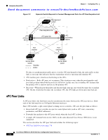
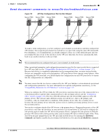
Chapter 7 Configuring vPCs Information About vPCs Send document comments to [email protected] • HSRP active-If you want to use HSRP and VLAN interfaces on the vPC peer devices, configure the primary vPC peer device with the HSRP active highest priority. Configure the secondary device to be the HSRP standby. And ensure that you have VLAN interfaces on each vPC device that are in the same administrative and operational mode. (See the "vPC Peer Links and Routing" section on page 7-25 for more information on vPC and HSRP.) We recommend that you configure Unidirectional Link Detection (UDLD) on both sides of the vPC peer link. See the "Configuring the UDLD Mode" section on page 2-39 for information on configuring UDLD. Configuring Layer 3 Backup Routes on a vPC Peer Link You can use VLAN network interfaces on the vPC peer devices to link to Layer 3 of the network for such applications as HSRP and PIM. However, we recommend that you configure a separate Layer 3 link for routing from the vPC peer devices, rather than using a VLAN network interface for this purpose. Note Ensure that you have a VLAN network interface configured on each peer device and that the interface is connected to the same VLAN on each device. Also, each VLAN interface must be in the same administrative and operational mode. For more information on configuring VLAN network interfaces, see Chapter 4, "Configuring Layer 3 Interfaces." If a failover occurs on the vPC peer link, the VLAN interfaces on the vPC peer devices are also affected. If a vPC peer link fails, the system brings down associated VLAN interfaces on the secondary vPC peer device. Beginning with Cisco NX-OS Release 4.2(1), you can ensure that specified VLAN interfaces do not go down on the vPC secondary device when the vPC peer link fails. Use the dual-active exclude interface-vlan command to configure this feature. Note When you attach a Layer 3 device to a vPC domain, the peering of routing protocols using a VLAN also carried on the vPC peer link is not supported. If routing protocol adjacencies are needed between vPC peer devices and a generic Layer 3 device, you must use physical routed interfaces for the interconnection. Use of the vPC peer-gateway feature does not change this requirement. Peer-Keepalive Link and Messages The Cisco NX-OS software uses the peer-keepalive link between the vPC peers to transmit periodic, configurable keepalive messages. You must have Layer 3 connectivity between the peer devices to transmit these messages; the system cannot bring up the vPC peer link unless the peer-keepalive link is already up and running. Note We recommend that you associate the vPC peer-keepalive link to a separate VRF mapped to a Layer 3 interface in each vPC peer device. If you do not configure a separate VRF, the system uses the management VRF and management ports by default. Do not use the peer link itself to send and receive vPC peer-keepalive messages. For more information on configuring VRFs, see the Cisco Nexus 7000 Series NX-OS Unicast Routing Configuration Guide, Release 5.x. OL-23435-03 Cisco Nexus 7000 Series NX-OS Interfaces Configuration Guide, Release 5.x 7-11
-
 1
1 -
2
-
3
-
4
-
5
-
6
-
7
-
8
-
9
-
10
-
11
-
12
-
13
-
14
-
15
-
16
-
17
-
18
-
19
-
20
-
21
-
22
-
23
-
24
-
25
-
26
-
27
-
28
-
29
-
30
-
31
-
32
-
33
-
34
-
35
-
36
-
37
-
38
-
39
-
40
-
41
-
42
-
43
-
44
-
45
-
46
-
47
-
48
-
49
-
50
-
51
-
52
-
53
-
54
-
55
-
56
-
57
-
58
-
59
-
60
-
61
-
62
-
63
-
64
-
65
-
66
-
67
-
68
-
69
-
70
-
71
-
72
-
73
-
74
-
75
-
76
-
77
-
78
-
79
-
80
-
81
-
82
-
83
-
84
-
85
-
86
-
87
-
88
-
89
-
90
-
91
-
92
-
93
-
94
-
95
-
96
-
97
-
98
-
99
-
100
-
101
-
102
-
103
-
104
-
105
-
106
-
107
-
108
-
109
-
110
-
111
-
112
-
113
-
114
-
115
-
116
-
117
-
118
-
119
-
120
-
121
-
122
-
123
-
124
-
125
-
126
-
127
-
128
-
129
-
130
-
131
-
132
-
133
-
134
-
135
-
136
-
137
-
138
-
139
-
140
-
141
-
142
-
143
-
144
-
145
-
146
-
147
-
148
-
149
-
150
-
151
-
152
-
153
-
154
-
155
-
156
-
157
-
158
-
159
-
160
-
161
-
162
-
163
-
164
-
165
-
166
-
167
-
168
-
169
-
170
-
171
-
172
-
173
-
174
-
175
-
176
-
177
-
178
-
179
-
180
-
181
-
182
-
183
-
184
-
185
-
186
-
187
-
188
-
189
-
190
-
191
-
192
-
193
-
194
-
195
-
196
-
197
-
198
-
199
-
200
-
201
-
202
-
203
-
204
-
205
-
206
-
207
-
 208
208 -
 209
209 -
 210
210 -
 211
211 -
 212
212 -
 213
213 -
 214
214 -
 215
215 -
 216
216 -
 217
217 -
 218
218 -
219
-
220
-
221
-
222
-
223
-
224
-
225
-
226
-
227
-
228
-
229
-
230
-
231
-
232
-
233
-
234
-
235
-
236
-
237
-
238
-
239
-
240
-
241
-
242
-
243
-
244
-
245
-
246
-
247
-
248
-
249
-
250
-
251
-
252
-
253
-
254
-
255
-
256
-
257
-
258
-
259
-
260
-
261
-
262
-
263
-
264
-
265
-
266
-
267
-
268
-
269
-
270
-
271
-
272
-
273
-
274
-
275
-
276
-
277
-
278
-
279
-
280
-
281
-
282
-
283
-
284
-
285
-
286
-
287
-
288
-
289
-
290
-
291
-
292
-
293
-
294
-
295
-
296
-
297
-
298
-
299
-
300
-
301
-
302
-
303
-
304
-
305
-
306
-
307
-
308
 |
 |