Cisco N7K-C7010 Configuration Guide - Page 238
Creating the vPC Peer Link, BEFORE YOU BEGIN
 |
UPC - 882658174445
View all Cisco N7K-C7010 manuals
Add to My Manuals
Save this manual to your list of manuals |
Page 238 highlights
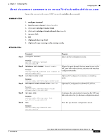
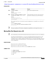
Configuring vPCs Chapter 7 Configuring vPCs Send document comments to [email protected] Step 3 Step 4 Command Purpose peer-keepalive destination ipaddress [hold-timeout secs | interval msecs {timeout secs} | {precedence {prec-value | network | internet | critical | flash-override | flash | immediate priority | routine}} | tos {tos-value | max-reliability | max-throughput | min-delay | min-monetary-cost | normal}} |tos-byte tos-byte-value} | source ipaddress | vrf {name | management vpc-keepalive}] Example: switch(config-vpc-domain)# peer-keepalive destination 172.28.230.85 switch(config-vpc-domain)# Configures the IPv4 address for the remote end of the vPC peer-keepalive link. Note The system does not form the vPC peer link until you configure a vPC peer-keepalive link, The management ports and VRF are the defaults Note We recommend that you configure a separate VRF and use a Layer 3 port from each vPC peer device in that VRF for the vPC peer-keepalive link. For more information on creating and configuring VRFs, see the Cisco Nexus 7000 Series NX-OS Unicast Routing Configuration Guide, Release 5.x. exit Exits the vpc-domain configuration mode. Step 5 Step 6 Example: switch(config-vpc-domain)# exit switch(config)# show vpc statistics Example: switch# show vpc statistics (Optional) Displays information about the configuration for the keepalive messages. copy running-config startup-config (Optional) Copies the running configuration to the Example: startup configuration. switch# copy running-config startup-config For more information on configuring VRFs, see the Cisco Nexus 7000 Series NX-OS Unicast Routing Configuration Guide, Release 5.x. This example shows how to configure the destination and source IP address and VRF for the vPC-peer-keepalive link: switch# configure terminal switch(config)# feature vpc switch(config)# vpc domain 100 switch(config-vpc-domain)# peer-keepalive destination 172.168.1.2 source 172.168.1.1 vrf vpc-keepalive Creating the vPC Peer Link You create the vPC peer link by designating the port channel that you want on each device as the peer link for the specified vPC domain. We recommend that you configure the Layer 2 port channels that you are designating as the vPC peer link in trunk mode and that you use two ports on separate modules on each vPC peer device for redundancy. BEFORE YOU BEGIN Ensure that you have enabled the vPC feature. Ensure that you are using a Layer 2 port channel. 7-36 Cisco Nexus 7000 Series NX-OS Interfaces Configuration Guide, Release 5.x OL-23435-03
-
 1
1 -
2
-
3
-
4
-
5
-
6
-
7
-
8
-
9
-
10
-
11
-
12
-
13
-
14
-
15
-
16
-
17
-
18
-
19
-
20
-
21
-
22
-
23
-
24
-
25
-
26
-
27
-
28
-
29
-
30
-
31
-
32
-
33
-
34
-
35
-
36
-
37
-
38
-
39
-
40
-
41
-
42
-
43
-
44
-
45
-
46
-
47
-
48
-
49
-
50
-
51
-
52
-
53
-
54
-
55
-
56
-
57
-
58
-
59
-
60
-
61
-
62
-
63
-
64
-
65
-
66
-
67
-
68
-
69
-
70
-
71
-
72
-
73
-
74
-
75
-
76
-
77
-
78
-
79
-
80
-
81
-
82
-
83
-
84
-
85
-
86
-
87
-
88
-
89
-
90
-
91
-
92
-
93
-
94
-
95
-
96
-
97
-
98
-
99
-
100
-
101
-
102
-
103
-
104
-
105
-
106
-
107
-
108
-
109
-
110
-
111
-
112
-
113
-
114
-
115
-
116
-
117
-
118
-
119
-
120
-
121
-
122
-
123
-
124
-
125
-
126
-
127
-
128
-
129
-
130
-
131
-
132
-
133
-
134
-
135
-
136
-
137
-
138
-
139
-
140
-
141
-
142
-
143
-
144
-
145
-
146
-
147
-
148
-
149
-
150
-
151
-
152
-
153
-
154
-
155
-
156
-
157
-
158
-
159
-
160
-
161
-
162
-
163
-
164
-
165
-
166
-
167
-
168
-
169
-
170
-
171
-
172
-
173
-
174
-
175
-
176
-
177
-
178
-
179
-
180
-
181
-
182
-
183
-
184
-
185
-
186
-
187
-
188
-
189
-
190
-
191
-
192
-
193
-
194
-
195
-
196
-
197
-
198
-
199
-
200
-
201
-
202
-
203
-
204
-
205
-
206
-
207
-
208
-
209
-
210
-
211
-
212
-
213
-
214
-
215
-
216
-
217
-
218
-
219
-
220
-
221
-
222
-
223
-
224
-
225
-
226
-
227
-
228
-
229
-
230
-
231
-
232
-
 233
233 -
 234
234 -
 235
235 -
 236
236 -
 237
237 -
 238
238 -
 239
239 -
 240
240 -
 241
241 -
 242
242 -
 243
243 -
244
-
245
-
246
-
247
-
248
-
249
-
250
-
251
-
252
-
253
-
254
-
255
-
256
-
257
-
258
-
259
-
260
-
261
-
262
-
263
-
264
-
265
-
266
-
267
-
268
-
269
-
270
-
271
-
272
-
273
-
274
-
275
-
276
-
277
-
278
-
279
-
280
-
281
-
282
-
283
-
284
-
285
-
286
-
287
-
288
-
289
-
290
-
291
-
292
-
293
-
294
-
295
-
296
-
297
-
298
-
299
-
300
-
301
-
302
-
303
-
304
-
305
-
306
-
307
-
308
 |
 |