Cisco N7K-C7010 Configuration Guide - Page 110
Routed Interfaces, Subinterfaces, High Availability, Virtualization Support,
 |
UPC - 882658174445
View all Cisco N7K-C7010 manuals
Add to My Manuals
Save this manual to your list of manuals |
Page 110 highlights
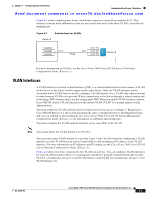
Information About Layer 3 Interfaces Chapter 4 Configuring Layer 3 Interfaces Send document comments to [email protected] • Tunnel Interfaces, page 4-4 • High Availability, page 4-4 • Virtualization Support, page 4-5 Routed Interfaces You can configure a port as a Layer 2 interface or a Layer 3 interface. A routed interface is a physical port that can route IP traffic to another device. A routed interface is a Layer 3 interface only and does not support Layer 2 protocols, such as the Spanning Tree Protocol (STP). All Ethernet ports are routed interfaces by default. You can change this default behavior with the CLI setup script or through the system default switchport command. You can assign an IP address to the port, enable routing, and assign routing protocol characteristics to this routed interface. Beginning with Cisco Release 4.2(1), you can assign a static MAC address to a Layer 3 interface. By default, the MAC address for the Layer 3 interfaces is the MAC address of the VDC it is assigned to. For information on configuring MAC addresses, see the Cisco Nexus 7000 Series NX-OS Layer 2 Switching Configuration Guide, Release 5.x. You can also create a Layer 3 port channel from routed interfaces. For more information on port channels, see Chapter 6, "Configuring Port Channels." Routed interfaces and subinterfaces support exponentially decayed rate counters. Cisco NX-OS tracks the following statistics with these averaging counters: • Input packets/sec • Output packets/sec • Input bytes/sec • Output bytes/sec Subinterfaces You can create virtual subinterfaces on a parent interface configured as a Layer 3 interface. A parent interface can be a physical port or a port channel. Subinterfaces divide the parent interface into two or more virtual interfaces on which you can assign unique Layer 3 parameters such as IP addresses and dynamic routing protocols. The IP address for each subinterface should be in a different subnet from any other subinterface on the parent interface. You create a subinterface with a name that consists of the parent interface name (for example, Ethernet 2/1) followed by a period and then by a number that is unique for that subinterface. For example, you could create a subinterface for Ethernet interface 2/1 named Ethernet 2/1.1 where .1 indicates the subinterface. Cisco NX-OS enables subinterfaces when the parent interface is enabled. You can shut down a subinterface independent of shutting down the parent interface. If you shut down the parent interface, Cisco NX-OS shuts down all associated subinterfaces as well. One use of subinterfaces is to provide unique Layer 3 interfaces to each virtual local area network (VLAN) supported by the parent interface. In this scenario, the parent interface connects to a Layer 2 trunking port on another device. You configure a subinterface and associate the subinterface to a VLAN ID using 802.1Q trunking. Cisco Nexus 7000 Series NX-OS Interfaces Configuration Guide, Release 5.x 4-2 OL-23435-03
-
 1
1 -
2
-
3
-
4
-
5
-
6
-
7
-
8
-
9
-
10
-
11
-
12
-
13
-
14
-
15
-
16
-
17
-
18
-
19
-
20
-
21
-
22
-
23
-
24
-
25
-
26
-
27
-
28
-
29
-
30
-
31
-
32
-
33
-
34
-
35
-
36
-
37
-
38
-
39
-
40
-
41
-
42
-
43
-
44
-
45
-
46
-
47
-
48
-
49
-
50
-
51
-
52
-
53
-
54
-
55
-
56
-
57
-
58
-
59
-
60
-
61
-
62
-
63
-
64
-
65
-
66
-
67
-
68
-
69
-
70
-
71
-
72
-
73
-
74
-
75
-
76
-
77
-
78
-
79
-
80
-
81
-
82
-
83
-
84
-
85
-
86
-
87
-
88
-
89
-
90
-
91
-
92
-
93
-
94
-
95
-
96
-
97
-
98
-
99
-
100
-
101
-
102
-
103
-
104
-
 105
105 -
 106
106 -
 107
107 -
 108
108 -
 109
109 -
 110
110 -
 111
111 -
 112
112 -
 113
113 -
 114
114 -
 115
115 -
116
-
117
-
118
-
119
-
120
-
121
-
122
-
123
-
124
-
125
-
126
-
127
-
128
-
129
-
130
-
131
-
132
-
133
-
134
-
135
-
136
-
137
-
138
-
139
-
140
-
141
-
142
-
143
-
144
-
145
-
146
-
147
-
148
-
149
-
150
-
151
-
152
-
153
-
154
-
155
-
156
-
157
-
158
-
159
-
160
-
161
-
162
-
163
-
164
-
165
-
166
-
167
-
168
-
169
-
170
-
171
-
172
-
173
-
174
-
175
-
176
-
177
-
178
-
179
-
180
-
181
-
182
-
183
-
184
-
185
-
186
-
187
-
188
-
189
-
190
-
191
-
192
-
193
-
194
-
195
-
196
-
197
-
198
-
199
-
200
-
201
-
202
-
203
-
204
-
205
-
206
-
207
-
208
-
209
-
210
-
211
-
212
-
213
-
214
-
215
-
216
-
217
-
218
-
219
-
220
-
221
-
222
-
223
-
224
-
225
-
226
-
227
-
228
-
229
-
230
-
231
-
232
-
233
-
234
-
235
-
236
-
237
-
238
-
239
-
240
-
241
-
242
-
243
-
244
-
245
-
246
-
247
-
248
-
249
-
250
-
251
-
252
-
253
-
254
-
255
-
256
-
257
-
258
-
259
-
260
-
261
-
262
-
263
-
264
-
265
-
266
-
267
-
268
-
269
-
270
-
271
-
272
-
273
-
274
-
275
-
276
-
277
-
278
-
279
-
280
-
281
-
282
-
283
-
284
-
285
-
286
-
287
-
288
-
289
-
290
-
291
-
292
-
293
-
294
-
295
-
296
-
297
-
298
-
299
-
300
-
301
-
302
-
303
-
304
-
305
-
306
-
307
-
308
 |
 |