Cisco N7K-C7010 Configuration Guide - Page 278
Q-in-Q Tunnel Ports, because one end is con d as an 802.1Q
 |
UPC - 882658174445
View all Cisco N7K-C7010 manuals
Add to My Manuals
Save this manual to your list of manuals |
Page 278 highlights
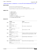
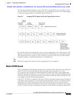
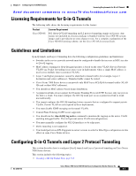
Information About Q-in-Q Tunnels Chapter 9 Configuring Q-in-Q VLAN Tunnels Send document comments to [email protected] Note Q-in-Q is supported on port channels and vPC. To configure a port channel as an asymmetrical link, all ports in the port channel must have the same tunneling configuration. Using the 802.1Q tunneling feature, service providers can use a single VLAN to support customers who have multiple VLANs. Customer VLAN IDs are preserved and traffic from different customers is segregated within the service-provider infrastructure even when they appear to be on the same VLAN. The 802.1Q tunneling expands VLAN space by using a VLAN-in-VLAN hierarchy and tagging the tagged packets. A port configured to support 802.1Q tunneling is called a tunnel port. When you configure tunneling, you assign a tunnel port to a VLAN that is dedicated to tunneling. Each customer requires a separate VLAN, but that VLAN supports all of the customer's VLANs. Customer traffic tagged in the normal way with appropriate VLAN IDs come from an 802.1Q trunk port on the customer device and into a tunnel port on the service-provider edge switch. The link between the customer device and the edge switch is an asymmetric link because one end is configured as an 802.1Q trunk port and the other end is configured as a tunnel port. You assign the tunnel port interface to an access VLAN ID unique to each customer. See Figure 9-1. Note Selective Q-in-Q tunneling is not supported. All frames entering the tunnel port will be subject to Q-in-Q tagging. Figure 9-1 802.1Q-in-Q Tunnel Ports Customer A VLANs 1 to 100 80820.21.Q1Qtrturnuknkpoprotrt 880022..11QQ ttrruunnkk ppoorrtt Tunnel port VLAN 30 Tunnel port VLAN 30 Trunk ports Service provider Tunnel port VLAN 30 Trunk ports 802.1Q trunk port Tunnel port VLAN 40 Tunnel port VLAN 40 Customer A VLANs 1 to 100 80820.21.Q1Qtrturnuknkpoprotrt 80820.21.Q1Qtrturnuknkpoprotrt 74016 Customer B VLANs 1 to 200 Trunk Asymmetric link Customer B VLANs 1 to 200 Packets entering the tunnel port on the service-provider edge switch, which are already 802.1Q-tagged with the appropriate VLAN IDs, are encapsulated with another layer of an 802.1Q tag that contains a VLAN ID unique to the customer. The original 802.1Q tag from the customer is preserved in the encapsulated packet. Therefore, packets that enter the service-provider infrastructure are double-tagged. Cisco Nexus 7000 Series NX-OS Interfaces Configuration Guide, Release 5.x 9-2 OL-23435-03
-
 1
1 -
2
-
3
-
4
-
5
-
6
-
7
-
8
-
9
-
10
-
11
-
12
-
13
-
14
-
15
-
16
-
17
-
18
-
19
-
20
-
21
-
22
-
23
-
24
-
25
-
26
-
27
-
28
-
29
-
30
-
31
-
32
-
33
-
34
-
35
-
36
-
37
-
38
-
39
-
40
-
41
-
42
-
43
-
44
-
45
-
46
-
47
-
48
-
49
-
50
-
51
-
52
-
53
-
54
-
55
-
56
-
57
-
58
-
59
-
60
-
61
-
62
-
63
-
64
-
65
-
66
-
67
-
68
-
69
-
70
-
71
-
72
-
73
-
74
-
75
-
76
-
77
-
78
-
79
-
80
-
81
-
82
-
83
-
84
-
85
-
86
-
87
-
88
-
89
-
90
-
91
-
92
-
93
-
94
-
95
-
96
-
97
-
98
-
99
-
100
-
101
-
102
-
103
-
104
-
105
-
106
-
107
-
108
-
109
-
110
-
111
-
112
-
113
-
114
-
115
-
116
-
117
-
118
-
119
-
120
-
121
-
122
-
123
-
124
-
125
-
126
-
127
-
128
-
129
-
130
-
131
-
132
-
133
-
134
-
135
-
136
-
137
-
138
-
139
-
140
-
141
-
142
-
143
-
144
-
145
-
146
-
147
-
148
-
149
-
150
-
151
-
152
-
153
-
154
-
155
-
156
-
157
-
158
-
159
-
160
-
161
-
162
-
163
-
164
-
165
-
166
-
167
-
168
-
169
-
170
-
171
-
172
-
173
-
174
-
175
-
176
-
177
-
178
-
179
-
180
-
181
-
182
-
183
-
184
-
185
-
186
-
187
-
188
-
189
-
190
-
191
-
192
-
193
-
194
-
195
-
196
-
197
-
198
-
199
-
200
-
201
-
202
-
203
-
204
-
205
-
206
-
207
-
208
-
209
-
210
-
211
-
212
-
213
-
214
-
215
-
216
-
217
-
218
-
219
-
220
-
221
-
222
-
223
-
224
-
225
-
226
-
227
-
228
-
229
-
230
-
231
-
232
-
233
-
234
-
235
-
236
-
237
-
238
-
239
-
240
-
241
-
242
-
243
-
244
-
245
-
246
-
247
-
248
-
249
-
250
-
251
-
252
-
253
-
254
-
255
-
256
-
257
-
258
-
259
-
260
-
261
-
262
-
263
-
264
-
265
-
266
-
267
-
268
-
269
-
270
-
271
-
272
-
 273
273 -
 274
274 -
 275
275 -
 276
276 -
 277
277 -
 278
278 -
 279
279 -
 280
280 -
 281
281 -
 282
282 -
 283
283 -
284
-
285
-
286
-
287
-
288
-
289
-
290
-
291
-
292
-
293
-
294
-
295
-
296
-
297
-
298
-
299
-
300
-
301
-
302
-
303
-
304
-
305
-
306
-
307
-
308
 |
 |