Cisco N7K-C7010 Configuration Guide - Page 211
shutdown, command, vPC Peer Configurations That Are Not Allowed
 |
UPC - 882658174445
View all Cisco N7K-C7010 manuals
Add to My Manuals
Save this manual to your list of manuals |
Page 211 highlights
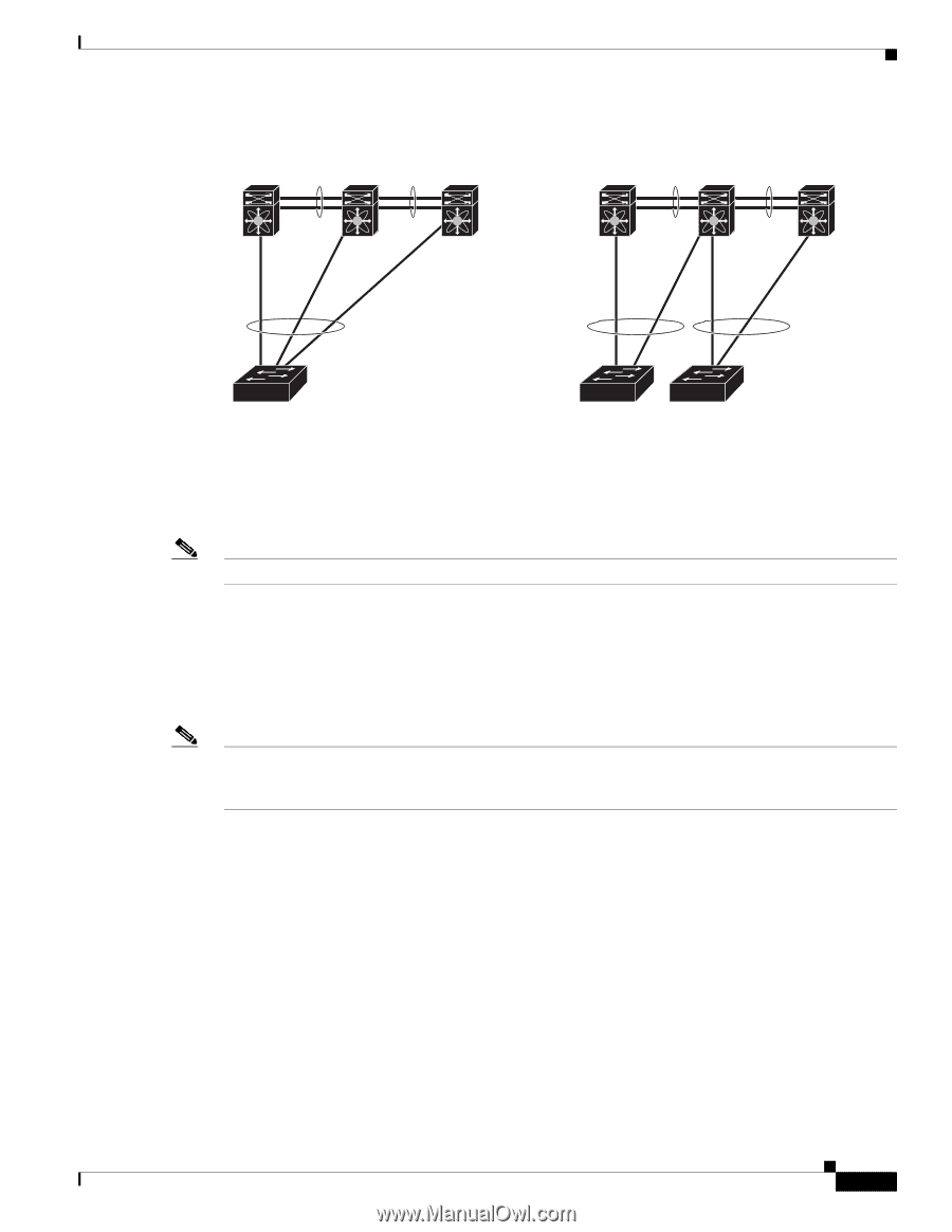
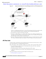
Chapter 7 Configuring vPCs Information About vPCs Send document comments to [email protected] Figure 7-8 Nexus 7000 device vPC Peer Configurations That Are Not Allowed Nexus 7000 Nexus 7000 device device Nexus 7000 device Nexus 7000 device Nexus 7000 device 273226 To make a valid configuration, you first configure a port channel on each device and then configure the vPC domain. You assign the port channel on each device as a peer link, using the same vPC domain ID. For redundancy, we recommend that you should configure at least two of the dedicated ports into the port channel because if one of the interfaces in the vPC peer link fails, the device automatically falls back to use another interface in the peer link. Note We recommend that you configure the Layer 2 port channels in trunk mode. Many operational parameters and configuration parameters must be the same in each device connected by a vPC peer link (see the "Compatibility Parameters for vPC Interfaces" section on page 7-15). Because each device is completely independent on the management plane, you must ensure that the devices are compatible on the critical parameters. vPC peer devices have separate control planes. After configuring the vPC peer link, you should display the configuration on each vPC peer device to ensure that the configurations are compatible. Note You must ensure that the two devices connected by the vPC peer link have certain identical operational and configuration parameters. For more information on required configuration consistency, see the "Compatibility Parameters for vPC Interfaces" section on page 7-15. When you configure the vPC peer link, the vPC peer devices negotiate that one of the connected devices is the primary device and the other connected device is the secondary device (see the "Configuring vPCs" section on page 7-30). The Cisco NX-OS software uses the lowest MAC address to elect the primary device. The software takes different actions on each device-that is, the primary and secondary-only in certain failover conditions. If the primary device fails, the secondary device becomes the new primary device when the system recovers, and the previously primary device is now the secondary device. You can also configure which of the vPC devices is the primary device. Changing the priority of the vPC peer devices can cause the interfaces in your network to go up and down. If you want to configure the role priority again to make one vPC device the primary device, configure the role priority on both the primary vPC device with a lower priority value, and secondary vPC device with the higher value. Then, shut down the port channel that is the vPC peer link on both devices by entering the shutdown command, and finally reenable the port channel on both devices by enter the no shutdown command. OL-23435-03 Cisco Nexus 7000 Series NX-OS Interfaces Configuration Guide, Release 5.x 7-9
-
 1
1 -
2
-
3
-
4
-
5
-
6
-
7
-
8
-
9
-
10
-
11
-
12
-
13
-
14
-
15
-
16
-
17
-
18
-
19
-
20
-
21
-
22
-
23
-
24
-
25
-
26
-
27
-
28
-
29
-
30
-
31
-
32
-
33
-
34
-
35
-
36
-
37
-
38
-
39
-
40
-
41
-
42
-
43
-
44
-
45
-
46
-
47
-
48
-
49
-
50
-
51
-
52
-
53
-
54
-
55
-
56
-
57
-
58
-
59
-
60
-
61
-
62
-
63
-
64
-
65
-
66
-
67
-
68
-
69
-
70
-
71
-
72
-
73
-
74
-
75
-
76
-
77
-
78
-
79
-
80
-
81
-
82
-
83
-
84
-
85
-
86
-
87
-
88
-
89
-
90
-
91
-
92
-
93
-
94
-
95
-
96
-
97
-
98
-
99
-
100
-
101
-
102
-
103
-
104
-
105
-
106
-
107
-
108
-
109
-
110
-
111
-
112
-
113
-
114
-
115
-
116
-
117
-
118
-
119
-
120
-
121
-
122
-
123
-
124
-
125
-
126
-
127
-
128
-
129
-
130
-
131
-
132
-
133
-
134
-
135
-
136
-
137
-
138
-
139
-
140
-
141
-
142
-
143
-
144
-
145
-
146
-
147
-
148
-
149
-
150
-
151
-
152
-
153
-
154
-
155
-
156
-
157
-
158
-
159
-
160
-
161
-
162
-
163
-
164
-
165
-
166
-
167
-
168
-
169
-
170
-
171
-
172
-
173
-
174
-
175
-
176
-
177
-
178
-
179
-
180
-
181
-
182
-
183
-
184
-
185
-
186
-
187
-
188
-
189
-
190
-
191
-
192
-
193
-
194
-
195
-
196
-
197
-
198
-
199
-
200
-
201
-
202
-
203
-
204
-
205
-
 206
206 -
 207
207 -
 208
208 -
 209
209 -
 210
210 -
 211
211 -
 212
212 -
 213
213 -
 214
214 -
 215
215 -
 216
216 -
217
-
218
-
219
-
220
-
221
-
222
-
223
-
224
-
225
-
226
-
227
-
228
-
229
-
230
-
231
-
232
-
233
-
234
-
235
-
236
-
237
-
238
-
239
-
240
-
241
-
242
-
243
-
244
-
245
-
246
-
247
-
248
-
249
-
250
-
251
-
252
-
253
-
254
-
255
-
256
-
257
-
258
-
259
-
260
-
261
-
262
-
263
-
264
-
265
-
266
-
267
-
268
-
269
-
270
-
271
-
272
-
273
-
274
-
275
-
276
-
277
-
278
-
279
-
280
-
281
-
282
-
283
-
284
-
285
-
286
-
287
-
288
-
289
-
290
-
291
-
292
-
293
-
294
-
295
-
296
-
297
-
298
-
299
-
300
-
301
-
302
-
303
-
304
-
305
-
306
-
307
-
308
 |
 |