Cisco N7K-C7010 Configuration Guide - Page 279
Native VLAN Hazard
 |
UPC - 882658174445
View all Cisco N7K-C7010 manuals
Add to My Manuals
Save this manual to your list of manuals |
Page 279 highlights
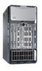
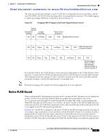
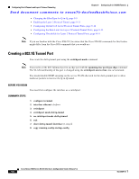
Chapter 9 Configuring Q-in-Q VLAN Tunnels Information About Q-in-Q Tunnels Send document comments to [email protected] The outer tag contains the customer's access VLAN ID (as assigned by the service provider), and the inner VLAN ID is the VLAN of the incoming traffic (as assigned by the customer). This double tagging is called tag stacking, Double-Q, or Q-in-Q as shown in Figure 9-2. Figure 9-2 Untagged, 802.1Q-Tagged, and Double-Tagged Ethernet Frames Source address Destination address Length/ EtherType DA SA Len/Etype Frame Check Sequence Data FCS Original Ethernet frame DA SA Etype Tag Len/Etype Data FCS 802.1Q frame from customer network DA SA Etype Tag Etype Tag Len/Etype Data FCS Double-tagged frame on trunk links between service provider network devices 79831 By using this method, the VLAN ID space of the outer tag is independent of the VLAN ID space of the inner tag. A single outer VLAN ID can represent the entire VLAN ID space for an individual customer. This technique allows the customer's Layer 2 network to extend across the service provider network, potentially creating a virtual LAN infrastructure over multiple sites. Note Hierarchical tagging, that is multi-level dot1q tagging Q-in-Q, is not supported. Native VLAN Hazard When configuring 802.1Q tunneling on an edge switch, you must use 802.1Q trunk ports for sending out packets into the service-provider network. However, packets that go through the core of the service-provider network might be carried through 802.1Q trunks, ISL trunks, or non-trunking links. When 802.1Q trunks are used in these core switches, the native VLANs of the 802.1Q trunks must not match any native VLAN of the dot1q-tunnel port on the same switch because traffic on the native VLAN is not tagged on the 802.1Q transmitting trunk port. In Figure 9-3, VLAN 40 is configured as the native VLAN for the 802.1Q trunk port from Customer X at the ingress edge switch in the service-provider network (Switch B). Switch A of Customer X sends a tagged packet on VLAN 30 to the ingress tunnel port of Switch B in the service-provider network belonging to access VLAN 40. Because the access VLAN of the tunnel port (VLAN 40) is the same as the native VLAN of the edge-switch trunk port (VLAN 40), the 802.1Q tag is not added to tagged packets OL-23435-03 Cisco Nexus 7000 Series NX-OS Interfaces Configuration Guide, Release 5.x 9-3
-
 1
1 -
2
-
3
-
4
-
5
-
6
-
7
-
8
-
9
-
10
-
11
-
12
-
13
-
14
-
15
-
16
-
17
-
18
-
19
-
20
-
21
-
22
-
23
-
24
-
25
-
26
-
27
-
28
-
29
-
30
-
31
-
32
-
33
-
34
-
35
-
36
-
37
-
38
-
39
-
40
-
41
-
42
-
43
-
44
-
45
-
46
-
47
-
48
-
49
-
50
-
51
-
52
-
53
-
54
-
55
-
56
-
57
-
58
-
59
-
60
-
61
-
62
-
63
-
64
-
65
-
66
-
67
-
68
-
69
-
70
-
71
-
72
-
73
-
74
-
75
-
76
-
77
-
78
-
79
-
80
-
81
-
82
-
83
-
84
-
85
-
86
-
87
-
88
-
89
-
90
-
91
-
92
-
93
-
94
-
95
-
96
-
97
-
98
-
99
-
100
-
101
-
102
-
103
-
104
-
105
-
106
-
107
-
108
-
109
-
110
-
111
-
112
-
113
-
114
-
115
-
116
-
117
-
118
-
119
-
120
-
121
-
122
-
123
-
124
-
125
-
126
-
127
-
128
-
129
-
130
-
131
-
132
-
133
-
134
-
135
-
136
-
137
-
138
-
139
-
140
-
141
-
142
-
143
-
144
-
145
-
146
-
147
-
148
-
149
-
150
-
151
-
152
-
153
-
154
-
155
-
156
-
157
-
158
-
159
-
160
-
161
-
162
-
163
-
164
-
165
-
166
-
167
-
168
-
169
-
170
-
171
-
172
-
173
-
174
-
175
-
176
-
177
-
178
-
179
-
180
-
181
-
182
-
183
-
184
-
185
-
186
-
187
-
188
-
189
-
190
-
191
-
192
-
193
-
194
-
195
-
196
-
197
-
198
-
199
-
200
-
201
-
202
-
203
-
204
-
205
-
206
-
207
-
208
-
209
-
210
-
211
-
212
-
213
-
214
-
215
-
216
-
217
-
218
-
219
-
220
-
221
-
222
-
223
-
224
-
225
-
226
-
227
-
228
-
229
-
230
-
231
-
232
-
233
-
234
-
235
-
236
-
237
-
238
-
239
-
240
-
241
-
242
-
243
-
244
-
245
-
246
-
247
-
248
-
249
-
250
-
251
-
252
-
253
-
254
-
255
-
256
-
257
-
258
-
259
-
260
-
261
-
262
-
263
-
264
-
265
-
266
-
267
-
268
-
269
-
270
-
271
-
272
-
273
-
 274
274 -
 275
275 -
 276
276 -
 277
277 -
 278
278 -
 279
279 -
 280
280 -
 281
281 -
 282
282 -
 283
283 -
 284
284 -
285
-
286
-
287
-
288
-
289
-
290
-
291
-
292
-
293
-
294
-
295
-
296
-
297
-
298
-
299
-
300
-
301
-
302
-
303
-
304
-
305
-
306
-
307
-
308
 |
 |