Cisco N7K-C7010 Configuration Guide - Page 205
show hardware, feature-capability, Link Aggregation Control Protocol LACP
 |
UPC - 882658174445
View all Cisco N7K-C7010 manuals
Add to My Manuals
Save this manual to your list of manuals |
Page 205 highlights
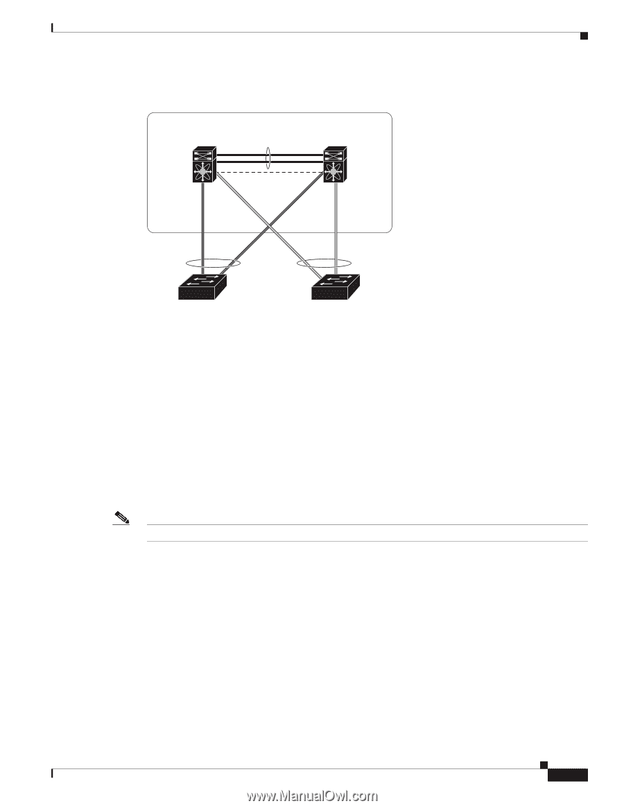
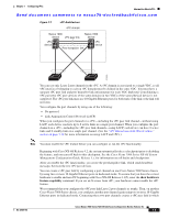
Chapter 7 Configuring vPCs Information About vPCs Send document comments to [email protected] Figure 7-1 vPC Architecture vPC domain Nexus 7000 Nexus 7000 device vPC peer link device vPC device Peer-keepalive link vPC device 273225 You can use only Layer 2 port channels in the vPC. A vPC domain is associated to a single VDC, so all vPC interfaces belonging to a given vPC domain must be defined in the same VDC. You must have a separate vPC peer link and peer-keepalive link infrastructure for each VDC deployed. Consolidating a vPC pair (two vPC peer devices of the same domain) in two VDCs of the same physical device is not supported. The vPC peer link must use 10-Gigabit Ethernet ports for both ends of the link or the link will not form. You configure the port channels by using one of the following: • No protocol • Link Aggregation Control Protocol (LACP) When you configure the port channels in a vPC-including the vPC peer link channel-without using LACP, each device can have up to 8 active links in a single port channel. When you configure the port channels in a vPC-including the vPC peer link channels-using LACP, each device can have 8 active links and 8 standby links in a single port channel. (See the "vPC Interactions with Other Features" section on page 7-20 for more information on using LACP and vPCs.) Note You must enable the vPC feature before you can configure or run the vPC functionality. Beginning with Cisco NX-OS Release 4.2, the system automatically takes a checkpoint prior to disabling the feature, and you can roll back to this checkpoint. See the Cisco Nexus 7000 Series NX-OS System Management Configuration Guide, Release 5.x, for information on roll backs and checkpoints. After you enable the vPC functionality, you create the peer-keepalive link, which sends heartbeat messages between the two vPC peer devices. You can create a vPC peer link by configuring a port channel on one Cisco Nexus 7000 Series chassis by using two or more 10-Gigabit Ethernet ports in dedicated mode. To ensure that you have the correct hardware to enable and run vPC beginning with Cisco NX-OS Release 4.1(5), enter the show hardware feature-capability command. If you see an X across from vPC, your hardware cannot enable the vPC feature. We recommend that you configure the vPC peer link Layer 2 port channels as trunks. Then, on another Cisco Nexus 7000 Series chassis, you configure another port channel again using two or more 10-Gigabit Ethernet ports in dedicated mode. Connecting these two port channels creates a vPC peer link in which OL-23435-03 Cisco Nexus 7000 Series NX-OS Interfaces Configuration Guide, Release 5.x 7-3
-
 1
1 -
2
-
3
-
4
-
5
-
6
-
7
-
8
-
9
-
10
-
11
-
12
-
13
-
14
-
15
-
16
-
17
-
18
-
19
-
20
-
21
-
22
-
23
-
24
-
25
-
26
-
27
-
28
-
29
-
30
-
31
-
32
-
33
-
34
-
35
-
36
-
37
-
38
-
39
-
40
-
41
-
42
-
43
-
44
-
45
-
46
-
47
-
48
-
49
-
50
-
51
-
52
-
53
-
54
-
55
-
56
-
57
-
58
-
59
-
60
-
61
-
62
-
63
-
64
-
65
-
66
-
67
-
68
-
69
-
70
-
71
-
72
-
73
-
74
-
75
-
76
-
77
-
78
-
79
-
80
-
81
-
82
-
83
-
84
-
85
-
86
-
87
-
88
-
89
-
90
-
91
-
92
-
93
-
94
-
95
-
96
-
97
-
98
-
99
-
100
-
101
-
102
-
103
-
104
-
105
-
106
-
107
-
108
-
109
-
110
-
111
-
112
-
113
-
114
-
115
-
116
-
117
-
118
-
119
-
120
-
121
-
122
-
123
-
124
-
125
-
126
-
127
-
128
-
129
-
130
-
131
-
132
-
133
-
134
-
135
-
136
-
137
-
138
-
139
-
140
-
141
-
142
-
143
-
144
-
145
-
146
-
147
-
148
-
149
-
150
-
151
-
152
-
153
-
154
-
155
-
156
-
157
-
158
-
159
-
160
-
161
-
162
-
163
-
164
-
165
-
166
-
167
-
168
-
169
-
170
-
171
-
172
-
173
-
174
-
175
-
176
-
177
-
178
-
179
-
180
-
181
-
182
-
183
-
184
-
185
-
186
-
187
-
188
-
189
-
190
-
191
-
192
-
193
-
194
-
195
-
196
-
197
-
198
-
199
-
 200
200 -
 201
201 -
 202
202 -
 203
203 -
 204
204 -
 205
205 -
 206
206 -
 207
207 -
 208
208 -
 209
209 -
 210
210 -
211
-
212
-
213
-
214
-
215
-
216
-
217
-
218
-
219
-
220
-
221
-
222
-
223
-
224
-
225
-
226
-
227
-
228
-
229
-
230
-
231
-
232
-
233
-
234
-
235
-
236
-
237
-
238
-
239
-
240
-
241
-
242
-
243
-
244
-
245
-
246
-
247
-
248
-
249
-
250
-
251
-
252
-
253
-
254
-
255
-
256
-
257
-
258
-
259
-
260
-
261
-
262
-
263
-
264
-
265
-
266
-
267
-
268
-
269
-
270
-
271
-
272
-
273
-
274
-
275
-
276
-
277
-
278
-
279
-
280
-
281
-
282
-
283
-
284
-
285
-
286
-
287
-
288
-
289
-
290
-
291
-
292
-
293
-
294
-
295
-
296
-
297
-
298
-
299
-
300
-
301
-
302
-
303
-
304
-
305
-
306
-
307
-
308
 |
 |