Cisco N7K-C7010 Configuration Guide - Page 206
track interface, Cisco Nexus 7000 Series NX-OS Unicast Routing Configuration, Guide, Release 5.x
 |
UPC - 882658174445
View all Cisco N7K-C7010 manuals
Add to My Manuals
Save this manual to your list of manuals |
Page 206 highlights
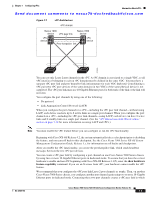
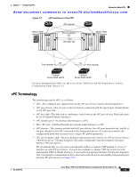
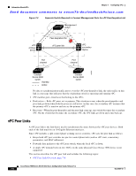
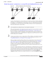
Information About vPCs Chapter 7 Configuring vPCs Send document comments to [email protected] the two linked Cisco Nexus devices appear as one device to a third device. The third device, or downstream device, can be a switch, server, or any other networking device that uses a regular port channel to connect to the vPC. If you are not using the correct module, the system displays an error message. Note We recommend that you configure the vPC peer links on dedicated ports of different modules to reduce the possibility of a failure. For the best resiliency scenario, use at least two modules. Beginning with Cisco NX-OS Release 4.2, if you must configure all the vPC peer links and core-facing interfaces on a single module, you should configure a track object that is associated with the Layer 3 link to the core and on all the links on the vPC peer link on both vPC peer devices. Once you configure this feature and if the primary vPC peer device fails, the system automatically suspends all the vPC links on the primary vPC peer device. This action forces all the vPC traffic to the secondary vPC peer device until the system stabilizes. Create a track object and apply that object to all links on the primary vPC peer device that connect to the core and to the vPC peer link. See the Cisco Nexus 7000 Series NX-OS Unicast Routing Configuration Guide, Release 5.x, for information on the track interface command. The vPC domain includes both vPC peer devices, the vPC peer-keepalive link, the vPC peer link, and all of the port channels in the vPC domain connected to the downstream device. You can have only one vPC domain ID on each device. In this version, you can connect each downstream device to a single vPC domain ID using a single port channel. Note Always attach all vPC devices using port channels to both vPC peer devices. A vPC (see Figure 7-2) provides the following benefits: • Allows a single device to use a port channel across two upstream devices • Eliminates Spanning Tree Protocol (STP) blocked ports • Provides a loop-free topology • Uses all available uplink bandwidth • Provides fast convergence if either the link or a device fails • Provides link-level resiliency • Assures high availability Cisco Nexus 7000 Series NX-OS Interfaces Configuration Guide, Release 5.x 7-4 OL-23435-03
-
 1
1 -
2
-
3
-
4
-
5
-
6
-
7
-
8
-
9
-
10
-
11
-
12
-
13
-
14
-
15
-
16
-
17
-
18
-
19
-
20
-
21
-
22
-
23
-
24
-
25
-
26
-
27
-
28
-
29
-
30
-
31
-
32
-
33
-
34
-
35
-
36
-
37
-
38
-
39
-
40
-
41
-
42
-
43
-
44
-
45
-
46
-
47
-
48
-
49
-
50
-
51
-
52
-
53
-
54
-
55
-
56
-
57
-
58
-
59
-
60
-
61
-
62
-
63
-
64
-
65
-
66
-
67
-
68
-
69
-
70
-
71
-
72
-
73
-
74
-
75
-
76
-
77
-
78
-
79
-
80
-
81
-
82
-
83
-
84
-
85
-
86
-
87
-
88
-
89
-
90
-
91
-
92
-
93
-
94
-
95
-
96
-
97
-
98
-
99
-
100
-
101
-
102
-
103
-
104
-
105
-
106
-
107
-
108
-
109
-
110
-
111
-
112
-
113
-
114
-
115
-
116
-
117
-
118
-
119
-
120
-
121
-
122
-
123
-
124
-
125
-
126
-
127
-
128
-
129
-
130
-
131
-
132
-
133
-
134
-
135
-
136
-
137
-
138
-
139
-
140
-
141
-
142
-
143
-
144
-
145
-
146
-
147
-
148
-
149
-
150
-
151
-
152
-
153
-
154
-
155
-
156
-
157
-
158
-
159
-
160
-
161
-
162
-
163
-
164
-
165
-
166
-
167
-
168
-
169
-
170
-
171
-
172
-
173
-
174
-
175
-
176
-
177
-
178
-
179
-
180
-
181
-
182
-
183
-
184
-
185
-
186
-
187
-
188
-
189
-
190
-
191
-
192
-
193
-
194
-
195
-
196
-
197
-
198
-
199
-
200
-
 201
201 -
 202
202 -
 203
203 -
 204
204 -
 205
205 -
 206
206 -
 207
207 -
 208
208 -
 209
209 -
 210
210 -
 211
211 -
212
-
213
-
214
-
215
-
216
-
217
-
218
-
219
-
220
-
221
-
222
-
223
-
224
-
225
-
226
-
227
-
228
-
229
-
230
-
231
-
232
-
233
-
234
-
235
-
236
-
237
-
238
-
239
-
240
-
241
-
242
-
243
-
244
-
245
-
246
-
247
-
248
-
249
-
250
-
251
-
252
-
253
-
254
-
255
-
256
-
257
-
258
-
259
-
260
-
261
-
262
-
263
-
264
-
265
-
266
-
267
-
268
-
269
-
270
-
271
-
272
-
273
-
274
-
275
-
276
-
277
-
278
-
279
-
280
-
281
-
282
-
283
-
284
-
285
-
286
-
287
-
288
-
289
-
290
-
291
-
292
-
293
-
294
-
295
-
296
-
297
-
298
-
299
-
300
-
301
-
302
-
303
-
304
-
305
-
306
-
307
-
308
 |
 |