Cisco N7K-C7010 Configuration Guide - Page 248
Configuring the Tracking Feature on a Single-Module vPC
 |
UPC - 882658174445
View all Cisco N7K-C7010 manuals
Add to My Manuals
Save this manual to your list of manuals |
Page 248 highlights
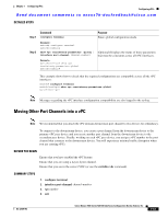
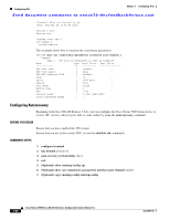
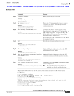
Configuring vPCs Chapter 7 Configuring vPCs Send document comments to [email protected] DETAILED STEPS Step 1 Command configure terminal Purpose Enters global configuration mode. Step 2 Step 3 Step 4 Example: switch# configure terminal switch(config)# vpc domain domain-id Example: switch(config)# vpc domain 5 switch(config-vpc-domain)# Enters the vPC domain number that you want to configure. The system enters the vpc-domain configuration mode. role priority priority Example: switch(config-vpc-domain)# role priority 4 switch(config-vpc-domain)# Enters the role priority that you want for the vPC system priority.The range of values is from 1 to 65636, and the default value is 32667. A lower value means this switch has a better chance of being the primary vPC. exit Exits the vpc-domain configuration mode. Step 5 Example: switch(config-vpc-domain)# exit switch(config)# show vpc role (Optional) Displays the vPC system priority. Step 6 Example: switch# show vpc role copy running-config startup-config (Optional) Copies the running configuration to the Example: startup configuration. switch# copy running-config startup-config This example shows how to manually configure the role priority of the vPC peer device: switch# configure terminal switch(config)# vpc domain 5 switch(config-vpc-domain)# role priority 4 Configuring the Tracking Feature on a Single-Module vPC Beginning with Cisco NX-OS Release 4.2, if you must configure all the vPC peer links and core-facing interfaces on a single module, you should configure a track object and a track list that is associated with the Layer 3 link to the core and on all the links on the vPC peer link on both primary vPC peer devices. Once you configure this feature and if the primary vPC peer device fails, the system automatically suspends all the vPC links on the primary vPC peer device. This action forces all the vPC traffic to the secondary vPC peer device until the system stabilizes. You must put this configuration on both vPC peer devices. Additionally, you should put the identical configuration on both vPC peer devices because either device can become the operationally primary vPC peer device. 7-46 Cisco Nexus 7000 Series NX-OS Interfaces Configuration Guide, Release 5.x OL-23435-03
-
 1
1 -
2
-
3
-
4
-
5
-
6
-
7
-
8
-
9
-
10
-
11
-
12
-
13
-
14
-
15
-
16
-
17
-
18
-
19
-
20
-
21
-
22
-
23
-
24
-
25
-
26
-
27
-
28
-
29
-
30
-
31
-
32
-
33
-
34
-
35
-
36
-
37
-
38
-
39
-
40
-
41
-
42
-
43
-
44
-
45
-
46
-
47
-
48
-
49
-
50
-
51
-
52
-
53
-
54
-
55
-
56
-
57
-
58
-
59
-
60
-
61
-
62
-
63
-
64
-
65
-
66
-
67
-
68
-
69
-
70
-
71
-
72
-
73
-
74
-
75
-
76
-
77
-
78
-
79
-
80
-
81
-
82
-
83
-
84
-
85
-
86
-
87
-
88
-
89
-
90
-
91
-
92
-
93
-
94
-
95
-
96
-
97
-
98
-
99
-
100
-
101
-
102
-
103
-
104
-
105
-
106
-
107
-
108
-
109
-
110
-
111
-
112
-
113
-
114
-
115
-
116
-
117
-
118
-
119
-
120
-
121
-
122
-
123
-
124
-
125
-
126
-
127
-
128
-
129
-
130
-
131
-
132
-
133
-
134
-
135
-
136
-
137
-
138
-
139
-
140
-
141
-
142
-
143
-
144
-
145
-
146
-
147
-
148
-
149
-
150
-
151
-
152
-
153
-
154
-
155
-
156
-
157
-
158
-
159
-
160
-
161
-
162
-
163
-
164
-
165
-
166
-
167
-
168
-
169
-
170
-
171
-
172
-
173
-
174
-
175
-
176
-
177
-
178
-
179
-
180
-
181
-
182
-
183
-
184
-
185
-
186
-
187
-
188
-
189
-
190
-
191
-
192
-
193
-
194
-
195
-
196
-
197
-
198
-
199
-
200
-
201
-
202
-
203
-
204
-
205
-
206
-
207
-
208
-
209
-
210
-
211
-
212
-
213
-
214
-
215
-
216
-
217
-
218
-
219
-
220
-
221
-
222
-
223
-
224
-
225
-
226
-
227
-
228
-
229
-
230
-
231
-
232
-
233
-
234
-
235
-
236
-
237
-
238
-
239
-
240
-
241
-
242
-
 243
243 -
 244
244 -
 245
245 -
 246
246 -
 247
247 -
 248
248 -
 249
249 -
 250
250 -
 251
251 -
 252
252 -
 253
253 -
254
-
255
-
256
-
257
-
258
-
259
-
260
-
261
-
262
-
263
-
264
-
265
-
266
-
267
-
268
-
269
-
270
-
271
-
272
-
273
-
274
-
275
-
276
-
277
-
278
-
279
-
280
-
281
-
282
-
283
-
284
-
285
-
286
-
287
-
288
-
289
-
290
-
291
-
292
-
293
-
294
-
295
-
296
-
297
-
298
-
299
-
300
-
301
-
302
-
303
-
304
-
305
-
306
-
307
-
308
 |
 |