Cisco N7K-C7010 Configuration Guide - Page 221
Configuring vPC Peer Links and Links to the Core on a Single Module
 |
UPC - 882658174445
View all Cisco N7K-C7010 manuals
Add to My Manuals
Save this manual to your list of manuals |
Page 221 highlights
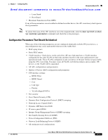
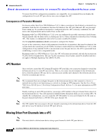
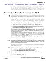
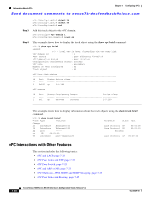
Chapter 7 Configuring vPCs Information About vPCs Send document comments to [email protected] To connect to the downstream device, you create a port channel to the downstream device from the primary vPC peer device and you create another port channel to the downstream device from the secondary peer device. Finally, working on each vPC peer device, you assign a vPC number to the port channel that connects to the downstream device. You will experience minimal traffic disruption when you are creating vPCs. Configuring vPC Peer Links and Links to the Core on a Single Module Note We recommend that you configure the vPC peer links on dedicated ports of different modules to reduce the possibility of a failure. For the best resiliency scenario, use at least two modules. Beginning with Cisco NX-OS Release 4.2, if you must configure all the vPC peer links and core-facing interfaces on a single module, you should configure, using the command line interface, a track object and a track list that is associated with the Layer 3 link to the core and on all vPC peer links on both vPC peer devices. You use this configuration to avoid dropping traffic if that particular module goes down because when all the tracked objects on the track list go down, the system does the following: • Stops the vPC primary peer device sending peer-keepalive messages which forces the vPC secondary peer device to take over. • Brings down all the downstream vPCs on that vPC peer device, which forces all the traffic to be rerouted in the access switch toward the other vPC peer device. Once you configure this feature and if the module fails, the system automatically suspends all the vPC links on the primary vPC peer device and stops the peer-keepalive messages. This action forces the vPC secondary device to take over the primary role and all the vPC traffic to go to this new vPC primary device until the system stabilizes. Create a track list that contains all the links to the core and all the vPC peer links as its object. Enable tracking for the specified vPC domain for this track list. Apply this same configuration to the other vPC peer device. See the Cisco Nexus 7000 Series NX-OS Unicast Routing Configuration Guide, Release 5.x, for information about configuring object tracking and track lists. See the Cisco Nexus 7000 Series NX-OS Unicast Routing Configuration Guide, Release 5.x, for information on configuring object tracking. Note This example uses boolean OR in the track list and will force all traffic to the vPC peer device only for a complete module failure. If you want to trigger a switchover when any core interface or peer-link goes down, use a boolean AND in the track list below. To configure a track list to switch over vPC to the remote peer when all related interfaces on a single module fail, follow these steps: Step 1 Step 2 Configure track objects on an interface (Layer 3 to core) and on a port channel (vPC peer link). n7k-1(config-if)# track 35 interface ethernet 8/35 line-protocol n7k-1(config-track)# track 23 interface ethernet 8/33 line-protocol n7k-1(config)# track 55 interface port-channel 100 line-protocol Create a track list that contains all the interfaces in the track list using the Boolean OR to trigger when all objects fail. n7k-1(config)# track 44 list boolean OR n7k-1(config-track)# object 23 OL-23435-03 Cisco Nexus 7000 Series NX-OS Interfaces Configuration Guide, Release 5.x 7-19
-
 1
1 -
2
-
3
-
4
-
5
-
6
-
7
-
8
-
9
-
10
-
11
-
12
-
13
-
14
-
15
-
16
-
17
-
18
-
19
-
20
-
21
-
22
-
23
-
24
-
25
-
26
-
27
-
28
-
29
-
30
-
31
-
32
-
33
-
34
-
35
-
36
-
37
-
38
-
39
-
40
-
41
-
42
-
43
-
44
-
45
-
46
-
47
-
48
-
49
-
50
-
51
-
52
-
53
-
54
-
55
-
56
-
57
-
58
-
59
-
60
-
61
-
62
-
63
-
64
-
65
-
66
-
67
-
68
-
69
-
70
-
71
-
72
-
73
-
74
-
75
-
76
-
77
-
78
-
79
-
80
-
81
-
82
-
83
-
84
-
85
-
86
-
87
-
88
-
89
-
90
-
91
-
92
-
93
-
94
-
95
-
96
-
97
-
98
-
99
-
100
-
101
-
102
-
103
-
104
-
105
-
106
-
107
-
108
-
109
-
110
-
111
-
112
-
113
-
114
-
115
-
116
-
117
-
118
-
119
-
120
-
121
-
122
-
123
-
124
-
125
-
126
-
127
-
128
-
129
-
130
-
131
-
132
-
133
-
134
-
135
-
136
-
137
-
138
-
139
-
140
-
141
-
142
-
143
-
144
-
145
-
146
-
147
-
148
-
149
-
150
-
151
-
152
-
153
-
154
-
155
-
156
-
157
-
158
-
159
-
160
-
161
-
162
-
163
-
164
-
165
-
166
-
167
-
168
-
169
-
170
-
171
-
172
-
173
-
174
-
175
-
176
-
177
-
178
-
179
-
180
-
181
-
182
-
183
-
184
-
185
-
186
-
187
-
188
-
189
-
190
-
191
-
192
-
193
-
194
-
195
-
196
-
197
-
198
-
199
-
200
-
201
-
202
-
203
-
204
-
205
-
206
-
207
-
208
-
209
-
210
-
211
-
212
-
213
-
214
-
215
-
 216
216 -
 217
217 -
 218
218 -
 219
219 -
 220
220 -
 221
221 -
 222
222 -
 223
223 -
 224
224 -
 225
225 -
 226
226 -
227
-
228
-
229
-
230
-
231
-
232
-
233
-
234
-
235
-
236
-
237
-
238
-
239
-
240
-
241
-
242
-
243
-
244
-
245
-
246
-
247
-
248
-
249
-
250
-
251
-
252
-
253
-
254
-
255
-
256
-
257
-
258
-
259
-
260
-
261
-
262
-
263
-
264
-
265
-
266
-
267
-
268
-
269
-
270
-
271
-
272
-
273
-
274
-
275
-
276
-
277
-
278
-
279
-
280
-
281
-
282
-
283
-
284
-
285
-
286
-
287
-
288
-
289
-
290
-
291
-
292
-
293
-
294
-
295
-
296
-
297
-
298
-
299
-
300
-
301
-
302
-
303
-
304
-
305
-
306
-
307
-
308
 |
 |