Cisco N7K-C7010 Configuration Guide - Page 207
vPC Terminology, vPC Interfaces in One VDC
 |
UPC - 882658174445
View all Cisco N7K-C7010 manuals
Add to My Manuals
Save this manual to your list of manuals |
Page 207 highlights
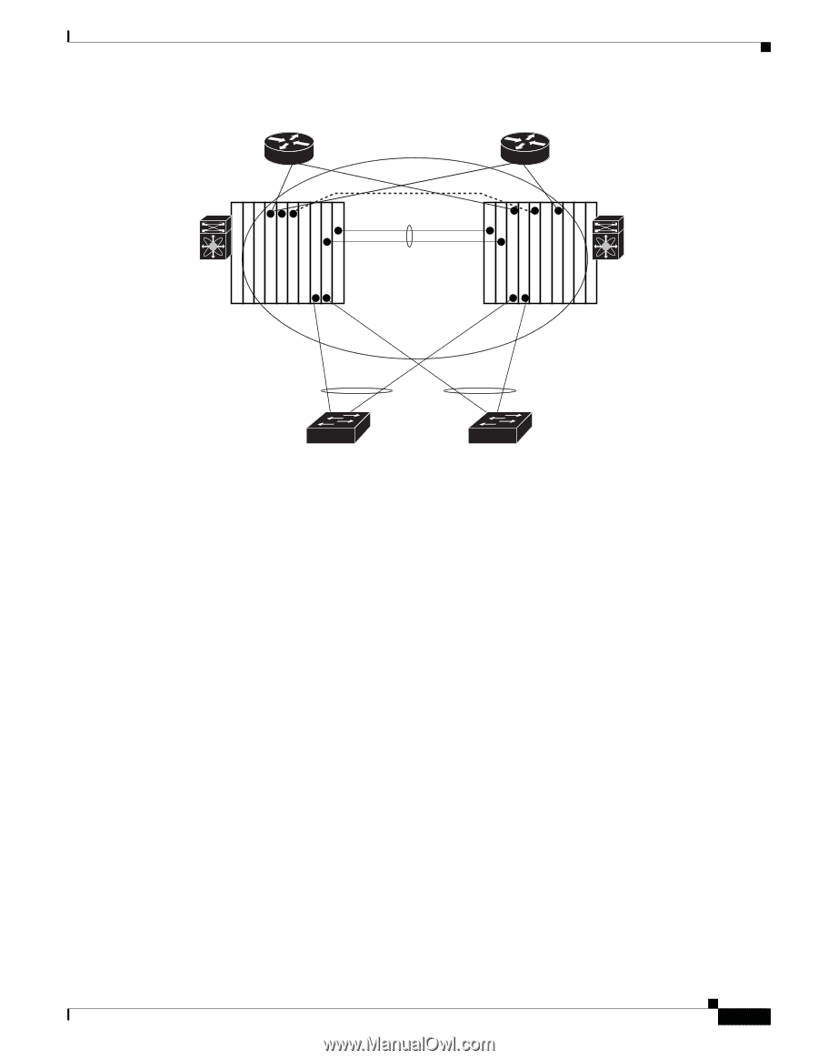
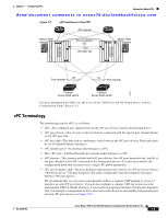
Chapter 7 Configuring vPCs Information About vPCs Send document comments to [email protected] Figure 7-2 vPC Interfaces in One VDC vPC domain Nexus 7000 device Peer-keepalive link 10 vPC peer link Nexus 7000 device Supervisor Supervisor Supervisor Supervisor 20 Port channel 21 Port channel 189976 Catalyst Series 6500 switch Catalyst Series 6500 switch For more information on VDCs, see the Cisco Nexus 7000 Series NX-OS Virtual Device Context Configuration Guide, Release 5.x. vPC Terminology The terminology used in vPCs is as follows: • vPC-The combined port channel between the vPC peer devices and the downstream device. • vPC peer device-One of a pair of devices that are connected with the special port channel known as the vPC peer link. • vPC peer link-The link used to synchronize states between the vPC peer devices. Both ends must be on 10-Gigabit Ethernet interfaces. • vPC member port-An interface that belongs to a vPC. • Host vPC port-A Fabric Extender host interfacesthat belongs to a vPC. • vPC domain-This domain includes both vPC peer devices, the vPC peer-keepalive link, and all of the port channels in the vPC connected to the downstream devices. It is also associated to the configuration mode that you must use to assign vPC global parameters. • vPC peer-keepalive link-The peer-keepalive link monitors the vitality of a vPC peer Cisco Nexus 7000 Series device. The peer-keepalive link sends configurable, periodic keepalive messages between vPC peer devices. We recommend that you associate a peer-keepalive link to a separate VRF mapped to a Layer 3 interface in each vPC peer device. If you do not configure a separate VRF, the system uses the management VRF by default. However, if you use the management interfaces for the peer-keepalive link, you must put a management switch connected to both the active and standby management ports on each vPC peer device (see Figure 7-9). OL-23435-03 Cisco Nexus 7000 Series NX-OS Interfaces Configuration Guide, Release 5.x 7-5
-
 1
1 -
2
-
3
-
4
-
5
-
6
-
7
-
8
-
9
-
10
-
11
-
12
-
13
-
14
-
15
-
16
-
17
-
18
-
19
-
20
-
21
-
22
-
23
-
24
-
25
-
26
-
27
-
28
-
29
-
30
-
31
-
32
-
33
-
34
-
35
-
36
-
37
-
38
-
39
-
40
-
41
-
42
-
43
-
44
-
45
-
46
-
47
-
48
-
49
-
50
-
51
-
52
-
53
-
54
-
55
-
56
-
57
-
58
-
59
-
60
-
61
-
62
-
63
-
64
-
65
-
66
-
67
-
68
-
69
-
70
-
71
-
72
-
73
-
74
-
75
-
76
-
77
-
78
-
79
-
80
-
81
-
82
-
83
-
84
-
85
-
86
-
87
-
88
-
89
-
90
-
91
-
92
-
93
-
94
-
95
-
96
-
97
-
98
-
99
-
100
-
101
-
102
-
103
-
104
-
105
-
106
-
107
-
108
-
109
-
110
-
111
-
112
-
113
-
114
-
115
-
116
-
117
-
118
-
119
-
120
-
121
-
122
-
123
-
124
-
125
-
126
-
127
-
128
-
129
-
130
-
131
-
132
-
133
-
134
-
135
-
136
-
137
-
138
-
139
-
140
-
141
-
142
-
143
-
144
-
145
-
146
-
147
-
148
-
149
-
150
-
151
-
152
-
153
-
154
-
155
-
156
-
157
-
158
-
159
-
160
-
161
-
162
-
163
-
164
-
165
-
166
-
167
-
168
-
169
-
170
-
171
-
172
-
173
-
174
-
175
-
176
-
177
-
178
-
179
-
180
-
181
-
182
-
183
-
184
-
185
-
186
-
187
-
188
-
189
-
190
-
191
-
192
-
193
-
194
-
195
-
196
-
197
-
198
-
199
-
200
-
201
-
 202
202 -
 203
203 -
 204
204 -
 205
205 -
 206
206 -
 207
207 -
 208
208 -
 209
209 -
 210
210 -
 211
211 -
 212
212 -
213
-
214
-
215
-
216
-
217
-
218
-
219
-
220
-
221
-
222
-
223
-
224
-
225
-
226
-
227
-
228
-
229
-
230
-
231
-
232
-
233
-
234
-
235
-
236
-
237
-
238
-
239
-
240
-
241
-
242
-
243
-
244
-
245
-
246
-
247
-
248
-
249
-
250
-
251
-
252
-
253
-
254
-
255
-
256
-
257
-
258
-
259
-
260
-
261
-
262
-
263
-
264
-
265
-
266
-
267
-
268
-
269
-
270
-
271
-
272
-
273
-
274
-
275
-
276
-
277
-
278
-
279
-
280
-
281
-
282
-
283
-
284
-
285
-
286
-
287
-
288
-
289
-
290
-
291
-
292
-
293
-
294
-
295
-
296
-
297
-
298
-
299
-
300
-
301
-
302
-
303
-
304
-
305
-
306
-
307
-
308
 |
 |