Cisco N7K-C7010 Configuration Guide - Page 224
show vpc brief, Fabric Services over Ethernet CFSoE. See
 |
UPC - 882658174445
View all Cisco N7K-C7010 manuals
Add to My Manuals
Save this manual to your list of manuals |
Page 224 highlights
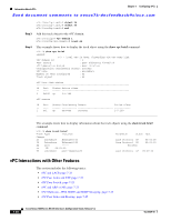
Information About vPCs Chapter 7 Configuring vPCs Send document comments to [email protected] STP is distributed; that is, the protocol continues running on both vPC peer devices. However, the configuration on the vPC peer device elected as the primary device controls the STP process for the vPC interfaces on the secondary vPC peer device. The primary vPC device synchronizes the STP state on the vPC secondary peer device using Cisco Fabric Services over Ethernet (CFSoE). See the "CFSoE" section on page 7-26 for information on CFSoE. The STP process for vPC also relies on the periodic keepalive messages to determine when one of the connected devices on the peer link fails. See the "Peer-Keepalive Link and Messages" section on page 7-11 for information on these messages. The vPC manager performs a proposal/handshake agreement between the vPC peer devices that set the primary and secondary devices and coordinates the two devices for STP. The primary vPC peer device then controls the STP protocol on both the primary and secondary devices. We recommend that you configure the primary vPC peer device as the STP primary root device and configure the secondary VPC device to be the STP secondary root device. If the primary vPC peer device fails over to the secondary vPC peer device, there is no change in the STP topology. The BPDUs uses the MAC address set for the vPC for the STP bridge ID in the designated bridge ID field. The vPC primary device sends these BPDUs on the vPC interfaces. You must configure both ends of vPC peer link with the identical STP configuration for the following parameters: • STP global settings: - STP mode - STP region configuration for MST - Enable/disable state per VLAN - Bridge Assurance setting - Port type setting - Loop Guard settings • STP interface settings: - Port type setting - Loop Guard - Root Guard Note If any of these parameters are misconfigured, the Cisco NX-OS software suspends all interfaces in the vPC. Check the syslog and enter the show vpc brief command to see if the vPC interfaces are suspended. Ensure that the following STP interface configurations are identical on both sides of the vPC peer links or you may see unpredictable behavior in the traffic flow: • BPDU Filter • BPDU Guard • Cost • Link type • Priority 7-22 Cisco Nexus 7000 Series NX-OS Interfaces Configuration Guide, Release 5.x OL-23435-03
-
 1
1 -
2
-
3
-
4
-
5
-
6
-
7
-
8
-
9
-
10
-
11
-
12
-
13
-
14
-
15
-
16
-
17
-
18
-
19
-
20
-
21
-
22
-
23
-
24
-
25
-
26
-
27
-
28
-
29
-
30
-
31
-
32
-
33
-
34
-
35
-
36
-
37
-
38
-
39
-
40
-
41
-
42
-
43
-
44
-
45
-
46
-
47
-
48
-
49
-
50
-
51
-
52
-
53
-
54
-
55
-
56
-
57
-
58
-
59
-
60
-
61
-
62
-
63
-
64
-
65
-
66
-
67
-
68
-
69
-
70
-
71
-
72
-
73
-
74
-
75
-
76
-
77
-
78
-
79
-
80
-
81
-
82
-
83
-
84
-
85
-
86
-
87
-
88
-
89
-
90
-
91
-
92
-
93
-
94
-
95
-
96
-
97
-
98
-
99
-
100
-
101
-
102
-
103
-
104
-
105
-
106
-
107
-
108
-
109
-
110
-
111
-
112
-
113
-
114
-
115
-
116
-
117
-
118
-
119
-
120
-
121
-
122
-
123
-
124
-
125
-
126
-
127
-
128
-
129
-
130
-
131
-
132
-
133
-
134
-
135
-
136
-
137
-
138
-
139
-
140
-
141
-
142
-
143
-
144
-
145
-
146
-
147
-
148
-
149
-
150
-
151
-
152
-
153
-
154
-
155
-
156
-
157
-
158
-
159
-
160
-
161
-
162
-
163
-
164
-
165
-
166
-
167
-
168
-
169
-
170
-
171
-
172
-
173
-
174
-
175
-
176
-
177
-
178
-
179
-
180
-
181
-
182
-
183
-
184
-
185
-
186
-
187
-
188
-
189
-
190
-
191
-
192
-
193
-
194
-
195
-
196
-
197
-
198
-
199
-
200
-
201
-
202
-
203
-
204
-
205
-
206
-
207
-
208
-
209
-
210
-
211
-
212
-
213
-
214
-
215
-
216
-
217
-
218
-
 219
219 -
 220
220 -
 221
221 -
 222
222 -
 223
223 -
 224
224 -
 225
225 -
 226
226 -
 227
227 -
 228
228 -
 229
229 -
230
-
231
-
232
-
233
-
234
-
235
-
236
-
237
-
238
-
239
-
240
-
241
-
242
-
243
-
244
-
245
-
246
-
247
-
248
-
249
-
250
-
251
-
252
-
253
-
254
-
255
-
256
-
257
-
258
-
259
-
260
-
261
-
262
-
263
-
264
-
265
-
266
-
267
-
268
-
269
-
270
-
271
-
272
-
273
-
274
-
275
-
276
-
277
-
278
-
279
-
280
-
281
-
282
-
283
-
284
-
285
-
286
-
287
-
288
-
289
-
290
-
291
-
292
-
293
-
294
-
295
-
296
-
297
-
298
-
299
-
300
-
301
-
302
-
303
-
304
-
305
-
306
-
307
-
308
 |
 |