Cisco N7K-C7010 Configuration Guide - Page 217
Compatibility Parameters for vPC Interfaces, show vpc consistency-parameters
 |
UPC - 882658174445
View all Cisco N7K-C7010 manuals
Add to My Manuals
Save this manual to your list of manuals |
Page 217 highlights
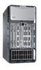
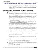
Chapter 7 Configuring vPCs Information About vPCs Send document comments to [email protected] Figure 7-10 FEX Straight-Through Topology (Host vPC) mgmt0 mgmt0 P0100 Eth1/1-2 FEX 100 Eth100/1/1 P0200 vPC200 Eth1/1-2 P0100 FEX 102 Eth102/1/5 281767 In the figure, each FEX is single-homed (straight-through FEX topology) with a Cisco Nexus 7000 Series Switch. The host interfaces on this FEX are configured as port channels and those port channels are configured as vPCs. Eth100/1/1 and Eth102/1/5 are configured as members of PO200, and PO200 is configured for vPC 200. In both topologies, port channels P020 and P0200 must be configured identically on the peer switches and configuration synchronization is used to synchronize the configurations of the vPC switches. See the Configuring the Cisco Nexus 2000 Series Fabric Extender for more information on configuring FEX ports. Compatibility Parameters for vPC Interfaces Many configuration and operational parameters must be identical on all interfaces in the vPC. We recommend that you configure the Layer 2 port channels that you use for the vPC peer link in trunk mode. After you enable the vPC feature and configure the peer link on both vPC peer devices, CFS messages provide a copy of the configuration on the local vPC peer device configuration to the remote vPC peer device. The system then determines whether any of the crucial configuration parameters differ on the two devices. (See the "CFSoE" section on page 7-26 for more information on CFS.) Note Enter the show vpc consistency-parameters command to display the configured values on all interfaces in the vPC. The displayed configurations are only those configurations that would limit the vPC peer link and vPC from coming up. The compatibility check process for vPCs differs from the compatibility check for regular port channels. See Chapter 6, "Configuring Port Channels," for information on regular port channels. OL-23435-03 Cisco Nexus 7000 Series NX-OS Interfaces Configuration Guide, Release 5.x 7-15
-
 1
1 -
2
-
3
-
4
-
5
-
6
-
7
-
8
-
9
-
10
-
11
-
12
-
13
-
14
-
15
-
16
-
17
-
18
-
19
-
20
-
21
-
22
-
23
-
24
-
25
-
26
-
27
-
28
-
29
-
30
-
31
-
32
-
33
-
34
-
35
-
36
-
37
-
38
-
39
-
40
-
41
-
42
-
43
-
44
-
45
-
46
-
47
-
48
-
49
-
50
-
51
-
52
-
53
-
54
-
55
-
56
-
57
-
58
-
59
-
60
-
61
-
62
-
63
-
64
-
65
-
66
-
67
-
68
-
69
-
70
-
71
-
72
-
73
-
74
-
75
-
76
-
77
-
78
-
79
-
80
-
81
-
82
-
83
-
84
-
85
-
86
-
87
-
88
-
89
-
90
-
91
-
92
-
93
-
94
-
95
-
96
-
97
-
98
-
99
-
100
-
101
-
102
-
103
-
104
-
105
-
106
-
107
-
108
-
109
-
110
-
111
-
112
-
113
-
114
-
115
-
116
-
117
-
118
-
119
-
120
-
121
-
122
-
123
-
124
-
125
-
126
-
127
-
128
-
129
-
130
-
131
-
132
-
133
-
134
-
135
-
136
-
137
-
138
-
139
-
140
-
141
-
142
-
143
-
144
-
145
-
146
-
147
-
148
-
149
-
150
-
151
-
152
-
153
-
154
-
155
-
156
-
157
-
158
-
159
-
160
-
161
-
162
-
163
-
164
-
165
-
166
-
167
-
168
-
169
-
170
-
171
-
172
-
173
-
174
-
175
-
176
-
177
-
178
-
179
-
180
-
181
-
182
-
183
-
184
-
185
-
186
-
187
-
188
-
189
-
190
-
191
-
192
-
193
-
194
-
195
-
196
-
197
-
198
-
199
-
200
-
201
-
202
-
203
-
204
-
205
-
206
-
207
-
208
-
209
-
210
-
211
-
 212
212 -
 213
213 -
 214
214 -
 215
215 -
 216
216 -
 217
217 -
 218
218 -
 219
219 -
 220
220 -
 221
221 -
 222
222 -
223
-
224
-
225
-
226
-
227
-
228
-
229
-
230
-
231
-
232
-
233
-
234
-
235
-
236
-
237
-
238
-
239
-
240
-
241
-
242
-
243
-
244
-
245
-
246
-
247
-
248
-
249
-
250
-
251
-
252
-
253
-
254
-
255
-
256
-
257
-
258
-
259
-
260
-
261
-
262
-
263
-
264
-
265
-
266
-
267
-
268
-
269
-
270
-
271
-
272
-
273
-
274
-
275
-
276
-
277
-
278
-
279
-
280
-
281
-
282
-
283
-
284
-
285
-
286
-
287
-
288
-
289
-
290
-
291
-
292
-
293
-
294
-
295
-
296
-
297
-
298
-
299
-
300
-
301
-
302
-
303
-
304
-
305
-
306
-
307
-
308
 |
 |