Dell PowerEdge T605 Hardware Owner's Manual (PDF) - Page 107
Expansion Cards, Removing an Expansion Card
 |
View all Dell PowerEdge T605 manuals
Add to My Manuals
Save this manual to your list of manuals |
Page 107 highlights
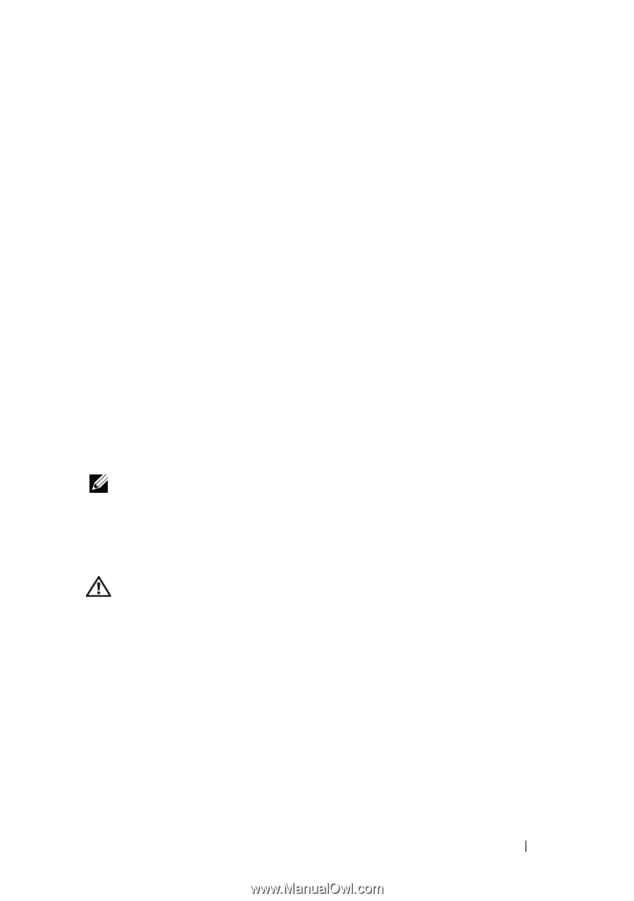
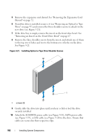
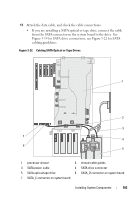
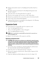
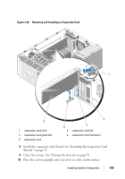
12 Replace the front drive bezel. See "Installing the Front Drive Bezel" on page 66. 13 Install the expansion card shroud. See "Installing the Expansion Card Shroud" on page 75. 14 Close the system. See "Closing the System" on page 70. 15 Place the system upright and on its feet on a flat, stable surface. 16 Reattach any peripherals, then connect the system to the electrical outlet. 17 Turn on the system and attached peripherals. 18 (Optional) Test the drive by running the system diagnostics. See "Running the System Diagnostics" on page 193. Expansion Cards The system board can accommodate up to five expansion cards: • One 3.3-V, full-length PCI-X (slot 5) • Three 3.3-V, half-length PCIe x4 (slots 1 through 3) • One 3.3-V, half-length PCIe x8 (slot 4) NOTE: Slot 1 is reserved for an optional RAC card and slot 2 is reserved for an optional SAS/RAID card. See Figure 6-1 for the location of the expansion card slots. Removing an Expansion Card CAUTION: Only trained service technicians are authorized to remove the system cover and access any of the components inside the system. Before performing any procedure, see your Product Information Guide for complete information about safety precautions, working inside the system and protecting against electrostatic discharge. 1 Turn off the system, including any attached peripherals, and disconnect the system from the electrical outlet and peripherals. 2 Open the system. See "Opening the System" on page 68. 3 Remove the expansion card shroud. See "Removing the Expansion Card Shroud" on page 72. 4 Open the expansion card latch adjacent to the slot. See Figure 3-26. Installing System Components 107
-
 1
1 -
2
-
3
-
4
-
5
-
6
-
7
-
8
-
9
-
10
-
11
-
12
-
13
-
14
-
15
-
16
-
17
-
18
-
19
-
20
-
21
-
22
-
23
-
24
-
25
-
26
-
27
-
28
-
29
-
30
-
31
-
32
-
33
-
34
-
35
-
36
-
37
-
38
-
39
-
40
-
41
-
42
-
43
-
44
-
45
-
46
-
47
-
48
-
49
-
50
-
51
-
52
-
53
-
54
-
55
-
56
-
57
-
58
-
59
-
60
-
61
-
62
-
63
-
64
-
65
-
66
-
67
-
68
-
69
-
70
-
71
-
72
-
73
-
74
-
75
-
76
-
77
-
78
-
79
-
80
-
81
-
82
-
83
-
84
-
85
-
86
-
87
-
88
-
89
-
90
-
91
-
92
-
93
-
94
-
95
-
96
-
97
-
98
-
99
-
100
-
101
-
 102
102 -
 103
103 -
 104
104 -
 105
105 -
 106
106 -
 107
107 -
 108
108 -
 109
109 -
 110
110 -
 111
111 -
 112
112 -
113
-
114
-
115
-
116
-
117
-
118
-
119
-
120
-
121
-
122
-
123
-
124
-
125
-
126
-
127
-
128
-
129
-
130
-
131
-
132
-
133
-
134
-
135
-
136
-
137
-
138
-
139
-
140
-
141
-
142
-
143
-
144
-
145
-
146
-
147
-
148
-
149
-
150
-
151
-
152
-
153
-
154
-
155
-
156
-
157
-
158
-
159
-
160
-
161
-
162
-
163
-
164
-
165
-
166
-
167
-
168
-
169
-
170
-
171
-
172
-
173
-
174
-
175
-
176
-
177
-
178
-
179
-
180
-
181
-
182
-
183
-
184
-
185
-
186
-
187
-
188
-
189
-
190
-
191
-
192
-
193
-
194
-
195
-
196
-
197
-
198
-
199
-
200
-
201
-
202
-
203
-
204
-
205
-
206
-
207
-
208
-
209
-
210
-
211
-
212
-
213
-
214
-
215
-
216
-
217
-
218
-
219
-
220
-
221
-
222
-
223
-
224
-
225
-
226
-
227
-
228
-
229
-
230
 |
 |