Dell PowerEdge T605 Hardware Owner's Manual (PDF) - Page 124
Installing the Expansion Card Fan, Removing the System Fan
 |
View all Dell PowerEdge T605 manuals
Add to My Manuals
Save this manual to your list of manuals |
Page 124 highlights
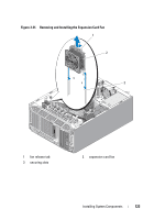
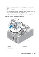
Installing the Expansion Card Fan CAUTION: Only trained service technicians are authorized to remove the system cover and access any of the components inside the system. Before performing any procedure, see your Product Information Guide for complete information about safety precautions, working inside the system and protecting against electrostatic discharge. 1 Hold the replacement fan with the fan cable on the top side, and align the edges of the fan with the securing slots on the chassis. 2 Slide the fan down into the securing slots until the fan release tab locks into place. See Figure 3-31. 3 Route the fan power cable through the adjacent slot in the chassis, and connect the cable to the FAN_1 connector on the system board (see Figure 6-1 for the connector location). 4 If a RAID battery was previously installed, re-install it. See "Installing a RAID Battery" on page 115. 5 Install the expansion card shroud. See "Installing the Expansion Card Shroud" on page 75. 6 Close the system. See "Closing the System" on page 70. 7 Place the system upright and on its feet on a flat, stable surface. 8 Reattach any peripherals, then connect the system to the electrical outlet. 9 Turn on the system and attached peripherals. Removing the System Fan CAUTION: Only trained service technicians are authorized to remove the system cover and access any of the components inside the system. Before performing any procedure, see your Product Information Guide for complete information about safety precautions, working inside the system and protecting against electrostatic discharge. 1 Turn off the system, including any attached peripherals, and disconnect the system from its electrical outlet and peripherals. 2 Open the system. See "Opening the System" on page 68. 3 Remove the expansion card shroud. See "Removing the Expansion Card Shroud" on page 72. 124 Installing System Components
-
 1
1 -
2
-
3
-
4
-
5
-
6
-
7
-
8
-
9
-
10
-
11
-
12
-
13
-
14
-
15
-
16
-
17
-
18
-
19
-
20
-
21
-
22
-
23
-
24
-
25
-
26
-
27
-
28
-
29
-
30
-
31
-
32
-
33
-
34
-
35
-
36
-
37
-
38
-
39
-
40
-
41
-
42
-
43
-
44
-
45
-
46
-
47
-
48
-
49
-
50
-
51
-
52
-
53
-
54
-
55
-
56
-
57
-
58
-
59
-
60
-
61
-
62
-
63
-
64
-
65
-
66
-
67
-
68
-
69
-
70
-
71
-
72
-
73
-
74
-
75
-
76
-
77
-
78
-
79
-
80
-
81
-
82
-
83
-
84
-
85
-
86
-
87
-
88
-
89
-
90
-
91
-
92
-
93
-
94
-
95
-
96
-
97
-
98
-
99
-
100
-
101
-
102
-
103
-
104
-
105
-
106
-
107
-
108
-
109
-
110
-
111
-
112
-
113
-
114
-
115
-
116
-
117
-
118
-
 119
119 -
 120
120 -
 121
121 -
 122
122 -
 123
123 -
 124
124 -
 125
125 -
 126
126 -
 127
127 -
 128
128 -
 129
129 -
130
-
131
-
132
-
133
-
134
-
135
-
136
-
137
-
138
-
139
-
140
-
141
-
142
-
143
-
144
-
145
-
146
-
147
-
148
-
149
-
150
-
151
-
152
-
153
-
154
-
155
-
156
-
157
-
158
-
159
-
160
-
161
-
162
-
163
-
164
-
165
-
166
-
167
-
168
-
169
-
170
-
171
-
172
-
173
-
174
-
175
-
176
-
177
-
178
-
179
-
180
-
181
-
182
-
183
-
184
-
185
-
186
-
187
-
188
-
189
-
190
-
191
-
192
-
193
-
194
-
195
-
196
-
197
-
198
-
199
-
200
-
201
-
202
-
203
-
204
-
205
-
206
-
207
-
208
-
209
-
210
-
211
-
212
-
213
-
214
-
215
-
216
-
217
-
218
-
219
-
220
-
221
-
222
-
223
-
224
-
225
-
226
-
227
-
228
-
229
-
230
 |
 |