Dell PowerEdge T605 Hardware Owner's Manual (PDF) - Page 156
Installing the System Board, the Optional Internal USB Memory Key
 |
View all Dell PowerEdge T605 manuals
Add to My Manuals
Save this manual to your list of manuals |
Page 156 highlights
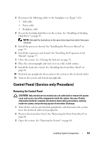
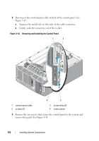
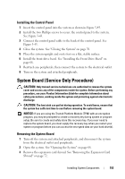
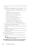
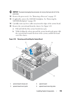
Installing the System Board 1 Align the back connectors on the system board with the cutouts in the back of the chassis. Ensure the system-board tray is square with the chassis so that the securing tabs on the chassis fully insert into the system-board securing slots. 2 Slide the system board towards the back of the system until the blue release pin locks into place. See Figure 3-44. 3 If applicable, install the SAS/SATA backplane. See "Installing the SAS/SATA Backplane" on page 150. 4 Install the processor(s). See "Installing a Processor" on page 136. 5 Install the memory modules in the same sockets from which they were removed. See "Installing Memory Modules" on page 130. 6 Install the TOE NIC hardware key, if previously present. See Figure 6-1 for the TOE_KEY socket location. 7 Install the internal USB memory key, if previously present. See "Installing the Optional Internal USB Memory Key" on page 120. 8 If applicable, install the SAS controller card. See "Installing a SAS Controller Card" on page 111. 9 If applicable, install the RAC card. See "Installing a RAC Card" on page 119. 10 If applicable, install the expansion cards and any attached cables. See "Installing an Expansion Card" on page 110. 11 Depending on your configuration, connect the following cables that you removed in "Removing the System Board" on page 153. See Figure 6-1 for connector locations. • Three power-supply cables to the PWR1, PWR2, and PWR3 connectors • I/O panel cable to the CTRL-PNL connector • SATA cable(s) to the SATA connector(s) • Diskette data cable to the FLOPPY connector • PATA data cable to IDE connector • Expansion card fan cable to the FAN1 connector • System fan cable to the FAN2 connector 156 Installing System Components
-
 1
1 -
2
-
3
-
4
-
5
-
6
-
7
-
8
-
9
-
10
-
11
-
12
-
13
-
14
-
15
-
16
-
17
-
18
-
19
-
20
-
21
-
22
-
23
-
24
-
25
-
26
-
27
-
28
-
29
-
30
-
31
-
32
-
33
-
34
-
35
-
36
-
37
-
38
-
39
-
40
-
41
-
42
-
43
-
44
-
45
-
46
-
47
-
48
-
49
-
50
-
51
-
52
-
53
-
54
-
55
-
56
-
57
-
58
-
59
-
60
-
61
-
62
-
63
-
64
-
65
-
66
-
67
-
68
-
69
-
70
-
71
-
72
-
73
-
74
-
75
-
76
-
77
-
78
-
79
-
80
-
81
-
82
-
83
-
84
-
85
-
86
-
87
-
88
-
89
-
90
-
91
-
92
-
93
-
94
-
95
-
96
-
97
-
98
-
99
-
100
-
101
-
102
-
103
-
104
-
105
-
106
-
107
-
108
-
109
-
110
-
111
-
112
-
113
-
114
-
115
-
116
-
117
-
118
-
119
-
120
-
121
-
122
-
123
-
124
-
125
-
126
-
127
-
128
-
129
-
130
-
131
-
132
-
133
-
134
-
135
-
136
-
137
-
138
-
139
-
140
-
141
-
142
-
143
-
144
-
145
-
146
-
147
-
148
-
149
-
150
-
 151
151 -
 152
152 -
 153
153 -
 154
154 -
 155
155 -
 156
156 -
 157
157 -
 158
158 -
 159
159 -
 160
160 -
 161
161 -
162
-
163
-
164
-
165
-
166
-
167
-
168
-
169
-
170
-
171
-
172
-
173
-
174
-
175
-
176
-
177
-
178
-
179
-
180
-
181
-
182
-
183
-
184
-
185
-
186
-
187
-
188
-
189
-
190
-
191
-
192
-
193
-
194
-
195
-
196
-
197
-
198
-
199
-
200
-
201
-
202
-
203
-
204
-
205
-
206
-
207
-
208
-
209
-
210
-
211
-
212
-
213
-
214
-
215
-
216
-
217
-
218
-
219
-
220
-
221
-
222
-
223
-
224
-
225
-
226
-
227
-
228
-
229
-
230
 |
 |