Dell PowerEdge T605 Hardware Owner's Manual (PDF) - Page 120
Internal USB Memory Key Connector, Installing the Optional Internal USB Memory Key
 |
View all Dell PowerEdge T605 manuals
Add to My Manuals
Save this manual to your list of manuals |
Page 120 highlights
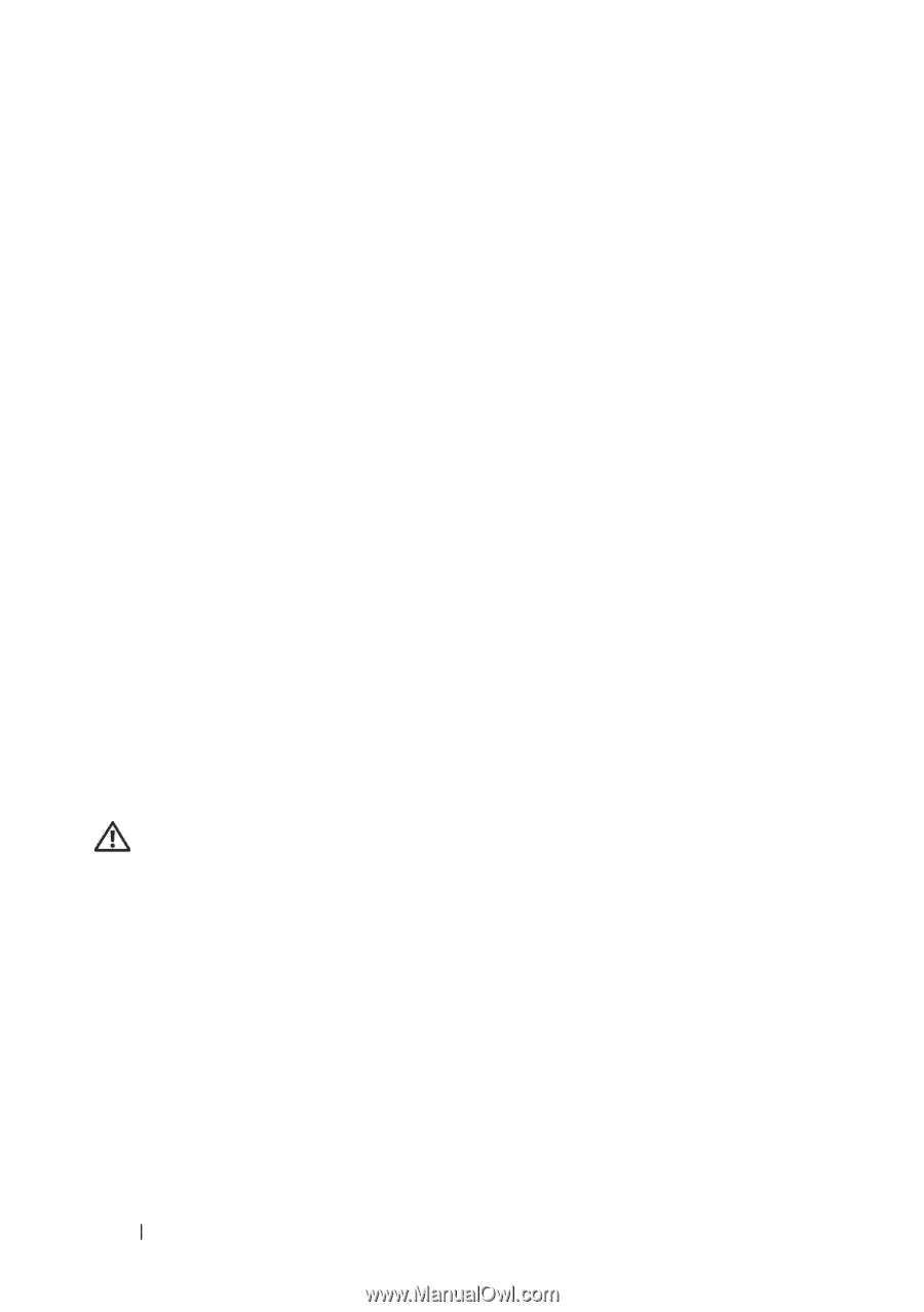
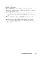
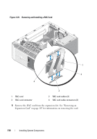
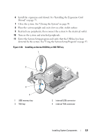
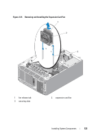
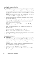
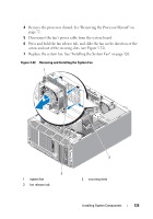
6 Install the expansion card shroud. See "Installing the Expansion Card Shroud" on page 75. 7 Close the system. See "Closing the System" on page 70. 8 Place the system upright and on its feet on a flat, stable surface. 9 Reattach any peripherals, then connect the system to the electrical outlet. 10 Turn on the system and attached peripherals. See the RAC card documentation for information on configuring and using the RAC card. Internal USB Memory Key Connector The system provides an internal USB connector located on the system board for use with a USB flash memory key. The USB memory key can be used as a boot device, security key, or mass storage device. To use the internal USB connector, the Internal USB Port option must be enabled in the Integrated Devices screen of the System Setup program. To boot from the USB memory key, you must configure the USB memory key with a boot image and then specify the USB memory key in the boot sequence in the System Setup program. See "System Setup Options" on page 44. For information on creating a bootable file on the USB memory key, see the user documentation that accompanied the USB memory key. Installing the Optional Internal USB Memory Key CAUTION: Only trained service technicians are authorized to remove the system cover and access any of the components inside the system. See your Product Information Guide for complete information about safety precautions, working inside the system, and protecting against electrostatic discharge. 1 Turn off the system, including any attached peripherals, and disconnect the system from its electrical outlet and peripherals. 2 Open the system. See "Opening the System" on page 68. 3 Remove the expansion card shroud. See "Removing the Expansion Card Shroud" on page 72. 4 Locate the USB connector on the system board (see Figure 6-1). 5 Insert the USB memory key into the USB connector on the board. See Figure 3-30. 120 Installing System Components
-
 1
1 -
2
-
3
-
4
-
5
-
6
-
7
-
8
-
9
-
10
-
11
-
12
-
13
-
14
-
15
-
16
-
17
-
18
-
19
-
20
-
21
-
22
-
23
-
24
-
25
-
26
-
27
-
28
-
29
-
30
-
31
-
32
-
33
-
34
-
35
-
36
-
37
-
38
-
39
-
40
-
41
-
42
-
43
-
44
-
45
-
46
-
47
-
48
-
49
-
50
-
51
-
52
-
53
-
54
-
55
-
56
-
57
-
58
-
59
-
60
-
61
-
62
-
63
-
64
-
65
-
66
-
67
-
68
-
69
-
70
-
71
-
72
-
73
-
74
-
75
-
76
-
77
-
78
-
79
-
80
-
81
-
82
-
83
-
84
-
85
-
86
-
87
-
88
-
89
-
90
-
91
-
92
-
93
-
94
-
95
-
96
-
97
-
98
-
99
-
100
-
101
-
102
-
103
-
104
-
105
-
106
-
107
-
108
-
109
-
110
-
111
-
112
-
113
-
114
-
 115
115 -
 116
116 -
 117
117 -
 118
118 -
 119
119 -
 120
120 -
 121
121 -
 122
122 -
 123
123 -
 124
124 -
 125
125 -
126
-
127
-
128
-
129
-
130
-
131
-
132
-
133
-
134
-
135
-
136
-
137
-
138
-
139
-
140
-
141
-
142
-
143
-
144
-
145
-
146
-
147
-
148
-
149
-
150
-
151
-
152
-
153
-
154
-
155
-
156
-
157
-
158
-
159
-
160
-
161
-
162
-
163
-
164
-
165
-
166
-
167
-
168
-
169
-
170
-
171
-
172
-
173
-
174
-
175
-
176
-
177
-
178
-
179
-
180
-
181
-
182
-
183
-
184
-
185
-
186
-
187
-
188
-
189
-
190
-
191
-
192
-
193
-
194
-
195
-
196
-
197
-
198
-
199
-
200
-
201
-
202
-
203
-
204
-
205
-
206
-
207
-
208
-
209
-
210
-
211
-
212
-
213
-
214
-
215
-
216
-
217
-
218
-
219
-
220
-
221
-
222
-
223
-
224
-
225
-
226
-
227
-
228
-
229
-
230
 |
 |