Dell PowerEdge T605 Hardware Owner's Manual (PDF) - Page 157
Install the front-drive bezel. See Installing the Front Drive Bezel
 |
View all Dell PowerEdge T605 manuals
Add to My Manuals
Save this manual to your list of manuals |
Page 157 highlights
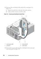
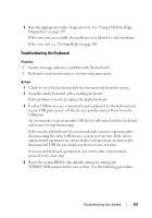
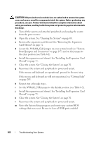
• SAS LED cable to the PERC_LED connector • SAS/SATA backplane cable to BP_12C connector • Intrusion switch cable to the INTRUSION connector 12 Close the system. See "Closing the System" on page 70. 13 Place the system upright and on its feet on a flat, stable surface. 14 Install the front-drive bezel. See "Installing the Front Drive Bezel" on page 66. 15 Reattach any peripherals, then connect the system to the electrical outlet. 16 Turn on the system and attached peripherals. Installing System Components 157
-
 1
1 -
2
-
3
-
4
-
5
-
6
-
7
-
8
-
9
-
10
-
11
-
12
-
13
-
14
-
15
-
16
-
17
-
18
-
19
-
20
-
21
-
22
-
23
-
24
-
25
-
26
-
27
-
28
-
29
-
30
-
31
-
32
-
33
-
34
-
35
-
36
-
37
-
38
-
39
-
40
-
41
-
42
-
43
-
44
-
45
-
46
-
47
-
48
-
49
-
50
-
51
-
52
-
53
-
54
-
55
-
56
-
57
-
58
-
59
-
60
-
61
-
62
-
63
-
64
-
65
-
66
-
67
-
68
-
69
-
70
-
71
-
72
-
73
-
74
-
75
-
76
-
77
-
78
-
79
-
80
-
81
-
82
-
83
-
84
-
85
-
86
-
87
-
88
-
89
-
90
-
91
-
92
-
93
-
94
-
95
-
96
-
97
-
98
-
99
-
100
-
101
-
102
-
103
-
104
-
105
-
106
-
107
-
108
-
109
-
110
-
111
-
112
-
113
-
114
-
115
-
116
-
117
-
118
-
119
-
120
-
121
-
122
-
123
-
124
-
125
-
126
-
127
-
128
-
129
-
130
-
131
-
132
-
133
-
134
-
135
-
136
-
137
-
138
-
139
-
140
-
141
-
142
-
143
-
144
-
145
-
146
-
147
-
148
-
149
-
150
-
151
-
 152
152 -
 153
153 -
 154
154 -
 155
155 -
 156
156 -
 157
157 -
 158
158 -
 159
159 -
 160
160 -
 161
161 -
 162
162 -
163
-
164
-
165
-
166
-
167
-
168
-
169
-
170
-
171
-
172
-
173
-
174
-
175
-
176
-
177
-
178
-
179
-
180
-
181
-
182
-
183
-
184
-
185
-
186
-
187
-
188
-
189
-
190
-
191
-
192
-
193
-
194
-
195
-
196
-
197
-
198
-
199
-
200
-
201
-
202
-
203
-
204
-
205
-
206
-
207
-
208
-
209
-
210
-
211
-
212
-
213
-
214
-
215
-
216
-
217
-
218
-
219
-
220
-
221
-
222
-
223
-
224
-
225
-
226
-
227
-
228
-
229
-
230
 |
 |

Installing System Components
157
•
SAS LED cable to the PERC_LED connector
•
SAS/SATA backplane cable to BP_12C connector
•
Intrusion switch cable to the INTRUSION connector
12
Close the system. See "Closing the System" on page 70.
13
Place the system upright and on its feet on a flat, stable surface.
14
Install the front-drive bezel. See "Installing the Front Drive Bezel" on
page 66.
15
Reattach any peripherals, then connect the system to the electrical outlet.
16
Turn on the system and attached peripherals.