Dell PowerEdge T605 Hardware Owner's Manual (PDF) - Page 48
CPU Information Screen, CPU Information
 |
View all Dell PowerEdge T605 manuals
Add to My Manuals
Save this manual to your list of manuals |
Page 48 highlights
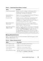
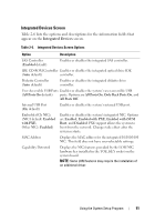
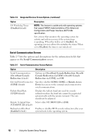
Table 2-3. Memory Information Screen (continued) Option Redundant Memory (Disabled default) Node Interleaving Memory Optimizer Technology (Enabled default) Description Enables or disables the redundant memory feature. When set to Spare Mode, the first rank of memory on each DIMM is reserved for memory sparing (see "Memory Sparing Support" on page 128). Redundant memory feature is disabled if the Node Interleaving field is enabled. If this field is enabled, memory interleaving is supported if a symmetric memory configuration is installed. If this field is set to disabled (the default), the system can support Non-Uniform Memory architecture (NUMA) (asymmetric) memory configurations. NOTE: The Node Interleaving field must be set to Disabled when using the redundant memory feature. Sets the behavior of the two DRAM controllers for memory optimization. When set to Enabled, the two controllers run in parallel 64-bit mode for improved memory performance (running single-bit ECC). When set to Disabled, the controllers are joined in 128-bit mode running multi-bit Advanced ECC, but memory performance is not optimized. CPU Information Screen Table 2-4 lists the options and descriptions for the information fields that appear on the CPU Information screen. Table 2-4. CPU Information Screen Option 64-bit Core Speed Bus Speed Description Specifies if the installed processors support 64-bit extensions. Displays the clock speed of the processors. Displays the bus speed of the processors. 48 Using the System Setup Program
-
 1
1 -
2
-
3
-
4
-
5
-
6
-
7
-
8
-
9
-
10
-
11
-
12
-
13
-
14
-
15
-
16
-
17
-
18
-
19
-
20
-
21
-
22
-
23
-
24
-
25
-
26
-
27
-
28
-
29
-
30
-
31
-
32
-
33
-
34
-
35
-
36
-
37
-
38
-
39
-
40
-
41
-
42
-
 43
43 -
 44
44 -
 45
45 -
 46
46 -
 47
47 -
 48
48 -
 49
49 -
 50
50 -
 51
51 -
 52
52 -
 53
53 -
54
-
55
-
56
-
57
-
58
-
59
-
60
-
61
-
62
-
63
-
64
-
65
-
66
-
67
-
68
-
69
-
70
-
71
-
72
-
73
-
74
-
75
-
76
-
77
-
78
-
79
-
80
-
81
-
82
-
83
-
84
-
85
-
86
-
87
-
88
-
89
-
90
-
91
-
92
-
93
-
94
-
95
-
96
-
97
-
98
-
99
-
100
-
101
-
102
-
103
-
104
-
105
-
106
-
107
-
108
-
109
-
110
-
111
-
112
-
113
-
114
-
115
-
116
-
117
-
118
-
119
-
120
-
121
-
122
-
123
-
124
-
125
-
126
-
127
-
128
-
129
-
130
-
131
-
132
-
133
-
134
-
135
-
136
-
137
-
138
-
139
-
140
-
141
-
142
-
143
-
144
-
145
-
146
-
147
-
148
-
149
-
150
-
151
-
152
-
153
-
154
-
155
-
156
-
157
-
158
-
159
-
160
-
161
-
162
-
163
-
164
-
165
-
166
-
167
-
168
-
169
-
170
-
171
-
172
-
173
-
174
-
175
-
176
-
177
-
178
-
179
-
180
-
181
-
182
-
183
-
184
-
185
-
186
-
187
-
188
-
189
-
190
-
191
-
192
-
193
-
194
-
195
-
196
-
197
-
198
-
199
-
200
-
201
-
202
-
203
-
204
-
205
-
206
-
207
-
208
-
209
-
210
-
211
-
212
-
213
-
214
-
215
-
216
-
217
-
218
-
219
-
220
-
221
-
222
-
223
-
224
-
225
-
226
-
227
-
228
-
229
-
230
 |
 |