Dell PowerEdge T605 Hardware Owner's Manual (PDF) - Page 133
Processors, Removing a Processor
 |
View all Dell PowerEdge T605 manuals
Add to My Manuals
Save this manual to your list of manuals |
Page 133 highlights
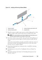
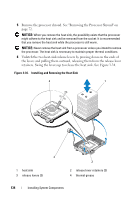
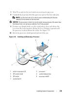
5 Locate the memory module sockets on the system board. See Figure 6-1. CAUTION: The DIMMs are hot to the touch for some time after the system has been powered down. Allow the DIMMs to cool before handling them. Handle the DIMMs by the card edges, and avoid touching the DIMM components. 6 Press down and out on the ejectors on each end of the socket until the memory module pops out of the socket. See Figure 3-33. 7 Install the processor shroud. See "Installing the Processor Shroud" on page 74. 8 Install the expansion card shroud. See "Installing the Expansion Card Shroud" on page 75. NOTICE: Never operate your system with the expansion shroud or processor shroud removed. Overheating of the system can develop quickly resulting in a shutdown of the system and the loss of data. 9 Close the system. See "Closing the System" on page 70. Processors You can upgrade your processor(s) to take advantage of future options in speed and functionality. Each processor and its associated internal cache memory are contained in a land grid array (LGA) package that is installed in a ZIF socket on the system board. Removing a Processor CAUTION: Only trained service technicians are authorized to remove the system cover and access any of the components inside the system. See your Product Information Guide for complete information about safety precautions, working inside the system, and protecting against electrostatic discharge. 1 Prior to upgrading your system, download the latest system BIOS version on support.dell.com. 2 Turn off the system, including any attached peripherals, and disconnect the system from the electrical outlet and peripherals. 3 Open the system. See "Opening the System" on page 68. 4 Remove the expansion card shroud. See "Removing the Expansion Card Shroud" on page 72. Installing System Components 133
-
 1
1 -
2
-
3
-
4
-
5
-
6
-
7
-
8
-
9
-
10
-
11
-
12
-
13
-
14
-
15
-
16
-
17
-
18
-
19
-
20
-
21
-
22
-
23
-
24
-
25
-
26
-
27
-
28
-
29
-
30
-
31
-
32
-
33
-
34
-
35
-
36
-
37
-
38
-
39
-
40
-
41
-
42
-
43
-
44
-
45
-
46
-
47
-
48
-
49
-
50
-
51
-
52
-
53
-
54
-
55
-
56
-
57
-
58
-
59
-
60
-
61
-
62
-
63
-
64
-
65
-
66
-
67
-
68
-
69
-
70
-
71
-
72
-
73
-
74
-
75
-
76
-
77
-
78
-
79
-
80
-
81
-
82
-
83
-
84
-
85
-
86
-
87
-
88
-
89
-
90
-
91
-
92
-
93
-
94
-
95
-
96
-
97
-
98
-
99
-
100
-
101
-
102
-
103
-
104
-
105
-
106
-
107
-
108
-
109
-
110
-
111
-
112
-
113
-
114
-
115
-
116
-
117
-
118
-
119
-
120
-
121
-
122
-
123
-
124
-
125
-
126
-
127
-
 128
128 -
 129
129 -
 130
130 -
 131
131 -
 132
132 -
 133
133 -
 134
134 -
 135
135 -
 136
136 -
 137
137 -
 138
138 -
139
-
140
-
141
-
142
-
143
-
144
-
145
-
146
-
147
-
148
-
149
-
150
-
151
-
152
-
153
-
154
-
155
-
156
-
157
-
158
-
159
-
160
-
161
-
162
-
163
-
164
-
165
-
166
-
167
-
168
-
169
-
170
-
171
-
172
-
173
-
174
-
175
-
176
-
177
-
178
-
179
-
180
-
181
-
182
-
183
-
184
-
185
-
186
-
187
-
188
-
189
-
190
-
191
-
192
-
193
-
194
-
195
-
196
-
197
-
198
-
199
-
200
-
201
-
202
-
203
-
204
-
205
-
206
-
207
-
208
-
209
-
210
-
211
-
212
-
213
-
214
-
215
-
216
-
217
-
218
-
219
-
220
-
221
-
222
-
223
-
224
-
225
-
226
-
227
-
228
-
229
-
230
 |
 |
