Dell PowerEdge T605 Hardware Owner's Manual (PDF) - Page 66
Front Drive Bezel, Removing the Front Drive Bezel
 |
View all Dell PowerEdge T605 manuals
Add to My Manuals
Save this manual to your list of manuals |
Page 66 highlights
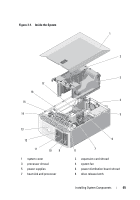
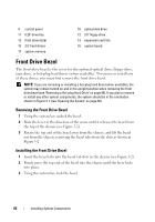
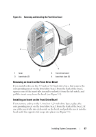
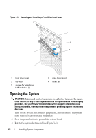
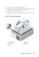
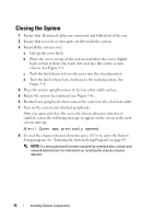
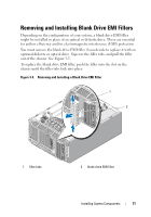
9 control panel 11 5.25" drive bay 13 front drive bezel 15 3.5" hard drives 17 system memory 10 optical disk drive 12 3.5" floppy drive 14 expansion card fan 16 system board Front Drive Bezel The front drive bezel is the cover for the optional optical drive, floppy drive, tape drive, or hot-plug hard drives (when available). To remove or install any of these drives, you must first remove the front drive bezel. NOTE: If you are removing or installing a hot-plug hard drive (when available), the system may remain turned on and in the upright position when removing the front drive bezel (see "Removing a Hot-plug Hard Drive" on page 88). If you plan to remove or install any other system components, the system should be in the orientation shown in Figure 3-1 (see "Opening the System" on page 68). Removing the Front Drive Bezel 1 Using the system key, unlock the bezel. 2 Slide the lever in the direction of the arrow until it releases the bezel from the top of the chassis (see Figure 3-2). 3 Rotate the top end of the bezel away from the chassis, and lift the bezel out from the chassis, removing the bezel tabs from the slots as shown in Figure 3-2. Installing the Front Drive Bezel 1 Insert the bezel tabs into the bezel tab slots in the chassis (see Figure 3-2). 2 Firmly press the top end of the bezel into the chassis until the lever locks into place. 3 Using the system key, lock the bezel. 66 Installing System Components
-
 1
1 -
2
-
3
-
4
-
5
-
6
-
7
-
8
-
9
-
10
-
11
-
12
-
13
-
14
-
15
-
16
-
17
-
18
-
19
-
20
-
21
-
22
-
23
-
24
-
25
-
26
-
27
-
28
-
29
-
30
-
31
-
32
-
33
-
34
-
35
-
36
-
37
-
38
-
39
-
40
-
41
-
42
-
43
-
44
-
45
-
46
-
47
-
48
-
49
-
50
-
51
-
52
-
53
-
54
-
55
-
56
-
57
-
58
-
59
-
60
-
 61
61 -
 62
62 -
 63
63 -
 64
64 -
 65
65 -
 66
66 -
 67
67 -
 68
68 -
 69
69 -
 70
70 -
 71
71 -
72
-
73
-
74
-
75
-
76
-
77
-
78
-
79
-
80
-
81
-
82
-
83
-
84
-
85
-
86
-
87
-
88
-
89
-
90
-
91
-
92
-
93
-
94
-
95
-
96
-
97
-
98
-
99
-
100
-
101
-
102
-
103
-
104
-
105
-
106
-
107
-
108
-
109
-
110
-
111
-
112
-
113
-
114
-
115
-
116
-
117
-
118
-
119
-
120
-
121
-
122
-
123
-
124
-
125
-
126
-
127
-
128
-
129
-
130
-
131
-
132
-
133
-
134
-
135
-
136
-
137
-
138
-
139
-
140
-
141
-
142
-
143
-
144
-
145
-
146
-
147
-
148
-
149
-
150
-
151
-
152
-
153
-
154
-
155
-
156
-
157
-
158
-
159
-
160
-
161
-
162
-
163
-
164
-
165
-
166
-
167
-
168
-
169
-
170
-
171
-
172
-
173
-
174
-
175
-
176
-
177
-
178
-
179
-
180
-
181
-
182
-
183
-
184
-
185
-
186
-
187
-
188
-
189
-
190
-
191
-
192
-
193
-
194
-
195
-
196
-
197
-
198
-
199
-
200
-
201
-
202
-
203
-
204
-
205
-
206
-
207
-
208
-
209
-
210
-
211
-
212
-
213
-
214
-
215
-
216
-
217
-
218
-
219
-
220
-
221
-
222
-
223
-
224
-
225
-
226
-
227
-
228
-
229
-
230
 |
 |