Dell PowerEdge T605 Hardware Owner's Manual (PDF) - Page 145
from the securing tabs, and lift the board out of the chassis. See,
 |
View all Dell PowerEdge T605 manuals
Add to My Manuals
Save this manual to your list of manuals |
Page 145 highlights
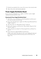
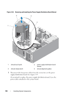
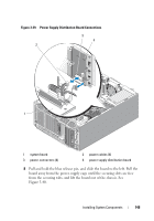
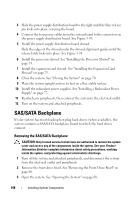
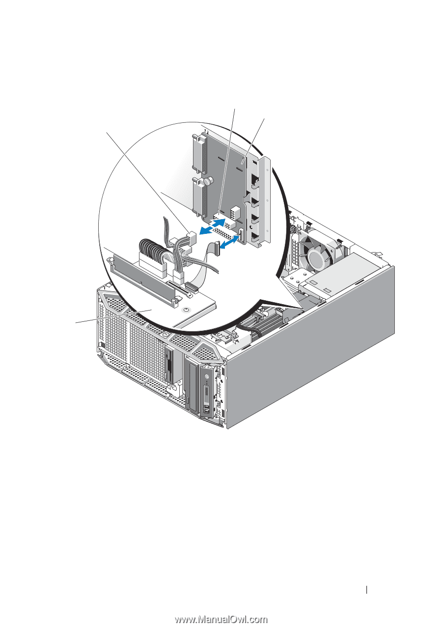
Figure 3-39. Power Supply Distribution Board Connections 3 4 2 1 1 system board 3 power connectors (4) 2 power cables (4) 4 power supply distribution board 8 Pull and hold the blue release pin, and slide the board to the left. Pull the board away from the power supply cage until the securing slots are free from the securing tabs, and lift the board out of the chassis. See Figure 3-40. Installing System Components 145
-
 1
1 -
2
-
3
-
4
-
5
-
6
-
7
-
8
-
9
-
10
-
11
-
12
-
13
-
14
-
15
-
16
-
17
-
18
-
19
-
20
-
21
-
22
-
23
-
24
-
25
-
26
-
27
-
28
-
29
-
30
-
31
-
32
-
33
-
34
-
35
-
36
-
37
-
38
-
39
-
40
-
41
-
42
-
43
-
44
-
45
-
46
-
47
-
48
-
49
-
50
-
51
-
52
-
53
-
54
-
55
-
56
-
57
-
58
-
59
-
60
-
61
-
62
-
63
-
64
-
65
-
66
-
67
-
68
-
69
-
70
-
71
-
72
-
73
-
74
-
75
-
76
-
77
-
78
-
79
-
80
-
81
-
82
-
83
-
84
-
85
-
86
-
87
-
88
-
89
-
90
-
91
-
92
-
93
-
94
-
95
-
96
-
97
-
98
-
99
-
100
-
101
-
102
-
103
-
104
-
105
-
106
-
107
-
108
-
109
-
110
-
111
-
112
-
113
-
114
-
115
-
116
-
117
-
118
-
119
-
120
-
121
-
122
-
123
-
124
-
125
-
126
-
127
-
128
-
129
-
130
-
131
-
132
-
133
-
134
-
135
-
136
-
137
-
138
-
139
-
 140
140 -
 141
141 -
 142
142 -
 143
143 -
 144
144 -
 145
145 -
 146
146 -
 147
147 -
 148
148 -
 149
149 -
 150
150 -
151
-
152
-
153
-
154
-
155
-
156
-
157
-
158
-
159
-
160
-
161
-
162
-
163
-
164
-
165
-
166
-
167
-
168
-
169
-
170
-
171
-
172
-
173
-
174
-
175
-
176
-
177
-
178
-
179
-
180
-
181
-
182
-
183
-
184
-
185
-
186
-
187
-
188
-
189
-
190
-
191
-
192
-
193
-
194
-
195
-
196
-
197
-
198
-
199
-
200
-
201
-
202
-
203
-
204
-
205
-
206
-
207
-
208
-
209
-
210
-
211
-
212
-
213
-
214
-
215
-
216
-
217
-
218
-
219
-
220
-
221
-
222
-
223
-
224
-
225
-
226
-
227
-
228
-
229
-
230
 |
 |
Installing System Components
145
Figure 3-39.
Power Supply Distribution Board Connections
8
Pull and hold the blue release pin, and slide the board to the left. Pull the
board away from the power supply cage until the securing slots are free
from the securing tabs, and lift the board out of the chassis. See
Figure 3-40.
1
system board
2
power cables (4)
3
power connectors (4)
4
power supply distribution board
2
1
3
4