Dell PowerEdge T605 Hardware Owner's Manual (PDF) - Page 112
Close the expansion-card retainer to secure the card in the system.
 |
View all Dell PowerEdge T605 manuals
Add to My Manuals
Save this manual to your list of manuals |
Page 112 highlights
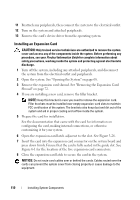
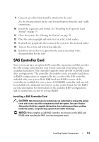
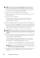
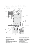
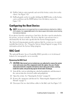
NOTE: If you are installing a replacement SAS/RAID card, do not remove the plastic cover protecting the card until after installation of the card is complete. 1 Turn off the system, including any attached peripherals, and disconnect the system from the electrical outlet and peripherals. 2 Open the system. See "Opening the System" on page 68. 3 Remove the expansion card shroud. See "Removing the Expansion Card Shroud" on page 72. 4 Prepare the card for installation. See the documentation that came with the card for information on configuring the card, making internal connections, or otherwise customizing it for your system. 5 Open the expansion card retainer adjacent to the slot. See Figure 3-26. 6 Insert the SAS card into the expansion card connector on the system board and press down firmly (a SAS/RAID card can only be installed in slot 2). See Figure 3-26. Ensure that the card is fully seated in the slot. See Figure 6-1 for the location of the expansion card slots on the system board. 7 Close the expansion-card retainer to secure the card in the system. NOTICE: Do not route card cables over or behind the cards. Cables routed over the cards can prevent the system cover from closing properly or cause damage to the equipment. 8 Your SAS controller card can either be cabled directly to the internal hard drives, or cabled to the SAS/SATA backplane if your system has a leverrelease hard drive bay (when available). Using the appropriate interface cable, attach one end of the cable to connector 0 on the SAS controller card and the other end to either the internal hard drives or the SAS/SATA backplane connector. - See Figure 3-12 for SAS cabling guidelines to the internal hard drives. - See Figure 3-27 for SAS cabling guidelines to the SAS/SATA backplane. NOTE: Be sure to connect the cable according to the connector labels on the cable. The cable is not operational if reversed. 9 If applicable, connect the LED cable from the SAS controller card to the system board connector (PERC_LED). See Figure 6-1 to locate the connector. 112 Installing System Components
-
 1
1 -
2
-
3
-
4
-
5
-
6
-
7
-
8
-
9
-
10
-
11
-
12
-
13
-
14
-
15
-
16
-
17
-
18
-
19
-
20
-
21
-
22
-
23
-
24
-
25
-
26
-
27
-
28
-
29
-
30
-
31
-
32
-
33
-
34
-
35
-
36
-
37
-
38
-
39
-
40
-
41
-
42
-
43
-
44
-
45
-
46
-
47
-
48
-
49
-
50
-
51
-
52
-
53
-
54
-
55
-
56
-
57
-
58
-
59
-
60
-
61
-
62
-
63
-
64
-
65
-
66
-
67
-
68
-
69
-
70
-
71
-
72
-
73
-
74
-
75
-
76
-
77
-
78
-
79
-
80
-
81
-
82
-
83
-
84
-
85
-
86
-
87
-
88
-
89
-
90
-
91
-
92
-
93
-
94
-
95
-
96
-
97
-
98
-
99
-
100
-
101
-
102
-
103
-
104
-
105
-
106
-
 107
107 -
 108
108 -
 109
109 -
 110
110 -
 111
111 -
 112
112 -
 113
113 -
 114
114 -
 115
115 -
 116
116 -
 117
117 -
118
-
119
-
120
-
121
-
122
-
123
-
124
-
125
-
126
-
127
-
128
-
129
-
130
-
131
-
132
-
133
-
134
-
135
-
136
-
137
-
138
-
139
-
140
-
141
-
142
-
143
-
144
-
145
-
146
-
147
-
148
-
149
-
150
-
151
-
152
-
153
-
154
-
155
-
156
-
157
-
158
-
159
-
160
-
161
-
162
-
163
-
164
-
165
-
166
-
167
-
168
-
169
-
170
-
171
-
172
-
173
-
174
-
175
-
176
-
177
-
178
-
179
-
180
-
181
-
182
-
183
-
184
-
185
-
186
-
187
-
188
-
189
-
190
-
191
-
192
-
193
-
194
-
195
-
196
-
197
-
198
-
199
-
200
-
201
-
202
-
203
-
204
-
205
-
206
-
207
-
208
-
209
-
210
-
211
-
212
-
213
-
214
-
215
-
216
-
217
-
218
-
219
-
220
-
221
-
222
-
223
-
224
-
225
-
226
-
227
-
228
-
229
-
230
 |
 |