Dell PowerEdge T605 Hardware Owner's Manual (PDF) - Page 95
FLOPPY on the system board. See for the connector location.
 |
View all Dell PowerEdge T605 manuals
Add to My Manuals
Save this manual to your list of manuals |
Page 95 highlights
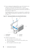
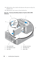
Figure 3-16. Installing Diskette Drive Shoulder Screws 1 1 screws (4) 10 From the front of the chassis, slide the drive into the drive bay until the shoulder screws fit into their slots and snap securely into the sliding plate. 11 Connect the power cable to the drive. 12 Connect the data cable from the drive to the diskette drive connector (FLOPPY) on the system board. See Figure 6-1 for the connector location. 13 Route the diskette drive data cable through the ribbon cable notch and ribbon cable guides in the processor shroud as shown in Figure 3-17. Installing System Components 95
-
 1
1 -
2
-
3
-
4
-
5
-
6
-
7
-
8
-
9
-
10
-
11
-
12
-
13
-
14
-
15
-
16
-
17
-
18
-
19
-
20
-
21
-
22
-
23
-
24
-
25
-
26
-
27
-
28
-
29
-
30
-
31
-
32
-
33
-
34
-
35
-
36
-
37
-
38
-
39
-
40
-
41
-
42
-
43
-
44
-
45
-
46
-
47
-
48
-
49
-
50
-
51
-
52
-
53
-
54
-
55
-
56
-
57
-
58
-
59
-
60
-
61
-
62
-
63
-
64
-
65
-
66
-
67
-
68
-
69
-
70
-
71
-
72
-
73
-
74
-
75
-
76
-
77
-
78
-
79
-
80
-
81
-
82
-
83
-
84
-
85
-
86
-
87
-
88
-
89
-
 90
90 -
 91
91 -
 92
92 -
 93
93 -
 94
94 -
 95
95 -
 96
96 -
 97
97 -
 98
98 -
 99
99 -
 100
100 -
101
-
102
-
103
-
104
-
105
-
106
-
107
-
108
-
109
-
110
-
111
-
112
-
113
-
114
-
115
-
116
-
117
-
118
-
119
-
120
-
121
-
122
-
123
-
124
-
125
-
126
-
127
-
128
-
129
-
130
-
131
-
132
-
133
-
134
-
135
-
136
-
137
-
138
-
139
-
140
-
141
-
142
-
143
-
144
-
145
-
146
-
147
-
148
-
149
-
150
-
151
-
152
-
153
-
154
-
155
-
156
-
157
-
158
-
159
-
160
-
161
-
162
-
163
-
164
-
165
-
166
-
167
-
168
-
169
-
170
-
171
-
172
-
173
-
174
-
175
-
176
-
177
-
178
-
179
-
180
-
181
-
182
-
183
-
184
-
185
-
186
-
187
-
188
-
189
-
190
-
191
-
192
-
193
-
194
-
195
-
196
-
197
-
198
-
199
-
200
-
201
-
202
-
203
-
204
-
205
-
206
-
207
-
208
-
209
-
210
-
211
-
212
-
213
-
214
-
215
-
216
-
217
-
218
-
219
-
220
-
221
-
222
-
223
-
224
-
225
-
226
-
227
-
228
-
229
-
230
 |
 |
Installing System Components
95
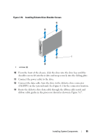
Figure 3-16.
Installing Diskette Drive Shoulder Screws
10
From the front of the chassis, slide the drive into the drive bay until the
shoulder screws fit into their slots and snap securely into the sliding plate.
11
Connect the power cable to the drive.
12
Connect the data cable from the drive to the diskette drive connector
(FLOPPY) on the system board. See Figure 6-1 for the connector location.
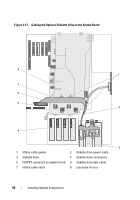
13
Route the diskette drive data cable through the ribbon cable notch and
ribbon cable guides in the processor shroud as shown in Figure 3-17.
1
screws (4)
1