Dell PowerEdge T605 Hardware Owner's Manual (PDF) - Page 75
Installing the Expansion Card Shroud, Power Supplies
 |
View all Dell PowerEdge T605 manuals
Add to My Manuals
Save this manual to your list of manuals |
Page 75 highlights
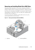
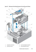
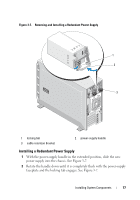
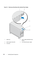
5 Install the expansion card shroud. See "Installing the Expansion Card Shroud" on page 75. 6 Close the system. See "Closing the System" on page 70. 7 Place the system upright and on its feet on a flat, stable surface. 8 Reattach any peripherals, then connect the system to the electrical outlet. 9 Turn on the system and attached peripherals. Installing the Expansion Card Shroud 1 Insert the rear shroud alignment tabs into the rear shroud tab slots, and then lower the shroud into the chassis. Align the front shroud alignment tab with the front shroud tab slot, and press downward on the shroud to lock the latch into place. See Figure 3-6. 2 Close the system. See "Closing the System" on page 70. 3 Place the system upright and on its feet on a flat, stable surface. 4 Reattach any peripherals, then connect the system to the electrical outlet. 5 Turn on the system and attached peripherals. Power Supplies Depending on your configuration, your system supports up to two hotpluggable redundant power supplies rated at 675 W, or a single non-redundant power supply rated at 650 W. If your system has redundant power supplies, see "Removing a Redundant Power Supply" on page 76 or "Installing a Redundant Power Supply" on page 77. If your system has a non-redundant power supply see "Removing a Non-redundant Power Supply" on page 78 or "Installing a Non-redundant Power Supply" on page 81. If two redundant power supplies are installed, the second power supply provides power redundancy. In redundant mode, the system distributes the power load across both power supplies to maximize efficiency. When a power supply is removed with the system powered on, the full power load is picked up by the remaining power supply. Installing System Components 75
-
 1
1 -
2
-
3
-
4
-
5
-
6
-
7
-
8
-
9
-
10
-
11
-
12
-
13
-
14
-
15
-
16
-
17
-
18
-
19
-
20
-
21
-
22
-
23
-
24
-
25
-
26
-
27
-
28
-
29
-
30
-
31
-
32
-
33
-
34
-
35
-
36
-
37
-
38
-
39
-
40
-
41
-
42
-
43
-
44
-
45
-
46
-
47
-
48
-
49
-
50
-
51
-
52
-
53
-
54
-
55
-
56
-
57
-
58
-
59
-
60
-
61
-
62
-
63
-
64
-
65
-
66
-
67
-
68
-
69
-
 70
70 -
 71
71 -
 72
72 -
 73
73 -
 74
74 -
 75
75 -
 76
76 -
 77
77 -
 78
78 -
 79
79 -
 80
80 -
81
-
82
-
83
-
84
-
85
-
86
-
87
-
88
-
89
-
90
-
91
-
92
-
93
-
94
-
95
-
96
-
97
-
98
-
99
-
100
-
101
-
102
-
103
-
104
-
105
-
106
-
107
-
108
-
109
-
110
-
111
-
112
-
113
-
114
-
115
-
116
-
117
-
118
-
119
-
120
-
121
-
122
-
123
-
124
-
125
-
126
-
127
-
128
-
129
-
130
-
131
-
132
-
133
-
134
-
135
-
136
-
137
-
138
-
139
-
140
-
141
-
142
-
143
-
144
-
145
-
146
-
147
-
148
-
149
-
150
-
151
-
152
-
153
-
154
-
155
-
156
-
157
-
158
-
159
-
160
-
161
-
162
-
163
-
164
-
165
-
166
-
167
-
168
-
169
-
170
-
171
-
172
-
173
-
174
-
175
-
176
-
177
-
178
-
179
-
180
-
181
-
182
-
183
-
184
-
185
-
186
-
187
-
188
-
189
-
190
-
191
-
192
-
193
-
194
-
195
-
196
-
197
-
198
-
199
-
200
-
201
-
202
-
203
-
204
-
205
-
206
-
207
-
208
-
209
-
210
-
211
-
212
-
213
-
214
-
215
-
216
-
217
-
218
-
219
-
220
-
221
-
222
-
223
-
224
-
225
-
226
-
227
-
228
-
229
-
230
 |
 |
