Dell PowerEdge T605 Hardware Owner's Manual (PDF) - Page 154
Remove all memory modules. See Removing Memory Modules on, If applicable
 |
View all Dell PowerEdge T605 manuals
Add to My Manuals
Save this manual to your list of manuals |
Page 154 highlights
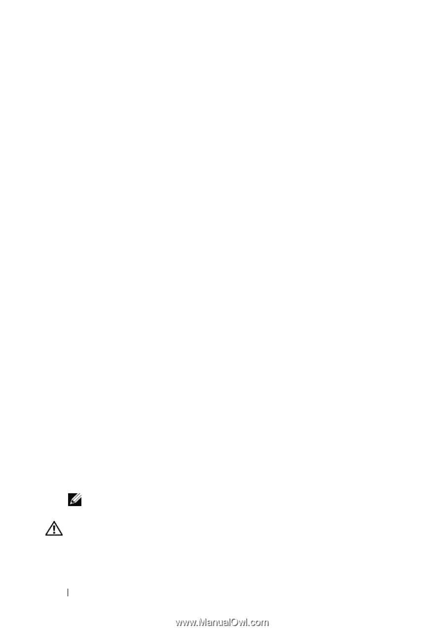
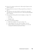
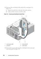
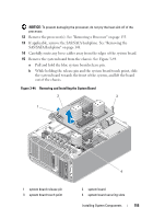
4 Remove the processor shroud. See "Removing the Processor Shroud" on page 72. 5 Depending on your configuration, disconnect the following cables from the system board. See Figure 6-1 for connector locations. • Three power-supply cables from the PWR1, PWR2, and PWR3 connectors • I/O panel cable from the CTRL_PNL connector • SATA cable(s) from the SATA connector(s) • Diskette data cable from the FLOPPY connector • PATA data cable from IDE connector • Expansion card fan cable from the FAN1 connector • System fan cable from the FAN2 connector • SAS LED cable from the PERC_LED connector • SAS/SATA backplane cable from BP_12C connector • Intrusion switch cable from the INTRUSION connector 6 If applicable, remove all expansion cards and any attached cables. See "Removing an Expansion Card" on page 107. 7 If applicable, remove the RAC card. See "Removing the RAC Card" on page 117. 8 If applicable, remove the SAS controller card. See "Removing a SAS Controller Card" on page 114. 9 Remove the internal USB memory key, if present. See Figure 6-1 for the USB socket location. 10 Remove the TOE hardware key, if present. See Figure 6-1 for the TOE_KEY socket location. 11 Remove all memory modules. See "Removing Memory Modules" on page 132. NOTE: Record the memory-module socket locations to ensure proper reinstallation of the memory modules. CAUTION: The processor and heat sink can become extremely hot. Allow sufficient time for the processor and heat sink to cool before handling. 154 Installing System Components
-
 1
1 -
2
-
3
-
4
-
5
-
6
-
7
-
8
-
9
-
10
-
11
-
12
-
13
-
14
-
15
-
16
-
17
-
18
-
19
-
20
-
21
-
22
-
23
-
24
-
25
-
26
-
27
-
28
-
29
-
30
-
31
-
32
-
33
-
34
-
35
-
36
-
37
-
38
-
39
-
40
-
41
-
42
-
43
-
44
-
45
-
46
-
47
-
48
-
49
-
50
-
51
-
52
-
53
-
54
-
55
-
56
-
57
-
58
-
59
-
60
-
61
-
62
-
63
-
64
-
65
-
66
-
67
-
68
-
69
-
70
-
71
-
72
-
73
-
74
-
75
-
76
-
77
-
78
-
79
-
80
-
81
-
82
-
83
-
84
-
85
-
86
-
87
-
88
-
89
-
90
-
91
-
92
-
93
-
94
-
95
-
96
-
97
-
98
-
99
-
100
-
101
-
102
-
103
-
104
-
105
-
106
-
107
-
108
-
109
-
110
-
111
-
112
-
113
-
114
-
115
-
116
-
117
-
118
-
119
-
120
-
121
-
122
-
123
-
124
-
125
-
126
-
127
-
128
-
129
-
130
-
131
-
132
-
133
-
134
-
135
-
136
-
137
-
138
-
139
-
140
-
141
-
142
-
143
-
144
-
145
-
146
-
147
-
148
-
 149
149 -
 150
150 -
 151
151 -
 152
152 -
 153
153 -
 154
154 -
 155
155 -
 156
156 -
 157
157 -
 158
158 -
 159
159 -
160
-
161
-
162
-
163
-
164
-
165
-
166
-
167
-
168
-
169
-
170
-
171
-
172
-
173
-
174
-
175
-
176
-
177
-
178
-
179
-
180
-
181
-
182
-
183
-
184
-
185
-
186
-
187
-
188
-
189
-
190
-
191
-
192
-
193
-
194
-
195
-
196
-
197
-
198
-
199
-
200
-
201
-
202
-
203
-
204
-
205
-
206
-
207
-
208
-
209
-
210
-
211
-
212
-
213
-
214
-
215
-
216
-
217
-
218
-
219
-
220
-
221
-
222
-
223
-
224
-
225
-
226
-
227
-
228
-
229
-
230
 |
 |