Dell PowerEdge T605 Hardware Owner's Manual (PDF) - Page 67
Removing an Insert on the Front Drive Bezel
 |
View all Dell PowerEdge T605 manuals
Add to My Manuals
Save this manual to your list of manuals |
Page 67 highlights
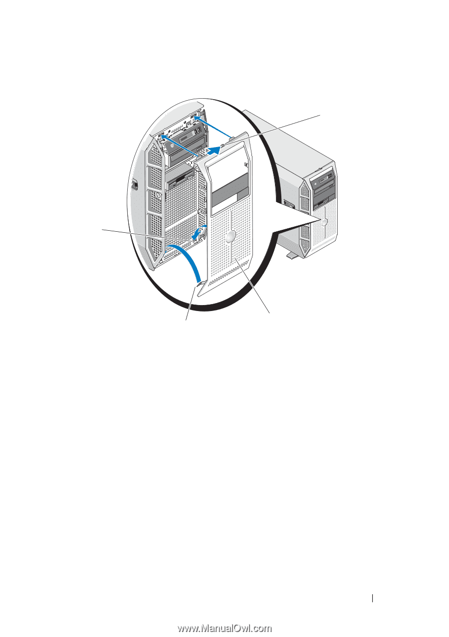
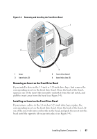
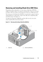
Figure 3-2. Removing and Installing the Front Drive Bezel 1 4 3 1 lever 3 bezel tabs (2) 2 2 front drive bezel 4 bezel tab slots (2) Removing an Insert on the Front Drive Bezel If you install a drive in the 3.5-inch or 5.25-inch drive bays, first remove the corresponding insert on the front drive bezel. From the back of the bezel, squeeze one of the insert tabs inward to unhook it from the tab notch, and pull the insert away from the bezel (see Figure 3-3). Installing an Insert on the Front Drive Bezel If you remove a drive in the 3.5-inch or 5.25-inch drive bays, replace the corresponding insert on the front drive bezel. From the back of the bezel, fit one of the insert tabs into a tab notch on the bezel, and push the insert into the bezel until the opposite tab snaps into place (see Figure 3-3). Installing System Components 67
-
 1
1 -
2
-
3
-
4
-
5
-
6
-
7
-
8
-
9
-
10
-
11
-
12
-
13
-
14
-
15
-
16
-
17
-
18
-
19
-
20
-
21
-
22
-
23
-
24
-
25
-
26
-
27
-
28
-
29
-
30
-
31
-
32
-
33
-
34
-
35
-
36
-
37
-
38
-
39
-
40
-
41
-
42
-
43
-
44
-
45
-
46
-
47
-
48
-
49
-
50
-
51
-
52
-
53
-
54
-
55
-
56
-
57
-
58
-
59
-
60
-
61
-
 62
62 -
 63
63 -
 64
64 -
 65
65 -
 66
66 -
 67
67 -
 68
68 -
 69
69 -
 70
70 -
 71
71 -
 72
72 -
73
-
74
-
75
-
76
-
77
-
78
-
79
-
80
-
81
-
82
-
83
-
84
-
85
-
86
-
87
-
88
-
89
-
90
-
91
-
92
-
93
-
94
-
95
-
96
-
97
-
98
-
99
-
100
-
101
-
102
-
103
-
104
-
105
-
106
-
107
-
108
-
109
-
110
-
111
-
112
-
113
-
114
-
115
-
116
-
117
-
118
-
119
-
120
-
121
-
122
-
123
-
124
-
125
-
126
-
127
-
128
-
129
-
130
-
131
-
132
-
133
-
134
-
135
-
136
-
137
-
138
-
139
-
140
-
141
-
142
-
143
-
144
-
145
-
146
-
147
-
148
-
149
-
150
-
151
-
152
-
153
-
154
-
155
-
156
-
157
-
158
-
159
-
160
-
161
-
162
-
163
-
164
-
165
-
166
-
167
-
168
-
169
-
170
-
171
-
172
-
173
-
174
-
175
-
176
-
177
-
178
-
179
-
180
-
181
-
182
-
183
-
184
-
185
-
186
-
187
-
188
-
189
-
190
-
191
-
192
-
193
-
194
-
195
-
196
-
197
-
198
-
199
-
200
-
201
-
202
-
203
-
204
-
205
-
206
-
207
-
208
-
209
-
210
-
211
-
212
-
213
-
214
-
215
-
216
-
217
-
218
-
219
-
220
-
221
-
222
-
223
-
224
-
225
-
226
-
227
-
228
-
229
-
230
 |
 |