Dell PowerEdge T605 Hardware Owner's Manual (PDF) - Page 146
To remove the power supply cage cover, pull the blue release pins until
 |
View all Dell PowerEdge T605 manuals
Add to My Manuals
Save this manual to your list of manuals |
Page 146 highlights
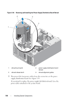
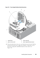
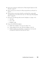
Figure 3-40. Removing and Installing the Power Supply Distribution Board 3 2 1 45 1 release pin 3 power supply distribution board 5 power supply cage 2 securing slots (4) 4 securing tabs (4) 9 If you intend to replace the redundant power supplies with a nonredundant power supply, install the power supply cage cover on the power supply cage. a Press the power supply cage cover into the power supply cage until the the blue release pins lock into the release pin alignment holes. See Figure 3-41. To remove the power supply cage cover, pull the blue release pins until the cover is free from the alignment holes, and lift the cover out of the chassis. 146 Installing System Components
-
 1
1 -
2
-
3
-
4
-
5
-
6
-
7
-
8
-
9
-
10
-
11
-
12
-
13
-
14
-
15
-
16
-
17
-
18
-
19
-
20
-
21
-
22
-
23
-
24
-
25
-
26
-
27
-
28
-
29
-
30
-
31
-
32
-
33
-
34
-
35
-
36
-
37
-
38
-
39
-
40
-
41
-
42
-
43
-
44
-
45
-
46
-
47
-
48
-
49
-
50
-
51
-
52
-
53
-
54
-
55
-
56
-
57
-
58
-
59
-
60
-
61
-
62
-
63
-
64
-
65
-
66
-
67
-
68
-
69
-
70
-
71
-
72
-
73
-
74
-
75
-
76
-
77
-
78
-
79
-
80
-
81
-
82
-
83
-
84
-
85
-
86
-
87
-
88
-
89
-
90
-
91
-
92
-
93
-
94
-
95
-
96
-
97
-
98
-
99
-
100
-
101
-
102
-
103
-
104
-
105
-
106
-
107
-
108
-
109
-
110
-
111
-
112
-
113
-
114
-
115
-
116
-
117
-
118
-
119
-
120
-
121
-
122
-
123
-
124
-
125
-
126
-
127
-
128
-
129
-
130
-
131
-
132
-
133
-
134
-
135
-
136
-
137
-
138
-
139
-
140
-
 141
141 -
 142
142 -
 143
143 -
 144
144 -
 145
145 -
 146
146 -
 147
147 -
 148
148 -
 149
149 -
 150
150 -
 151
151 -
152
-
153
-
154
-
155
-
156
-
157
-
158
-
159
-
160
-
161
-
162
-
163
-
164
-
165
-
166
-
167
-
168
-
169
-
170
-
171
-
172
-
173
-
174
-
175
-
176
-
177
-
178
-
179
-
180
-
181
-
182
-
183
-
184
-
185
-
186
-
187
-
188
-
189
-
190
-
191
-
192
-
193
-
194
-
195
-
196
-
197
-
198
-
199
-
200
-
201
-
202
-
203
-
204
-
205
-
206
-
207
-
208
-
209
-
210
-
211
-
212
-
213
-
214
-
215
-
216
-
217
-
218
-
219
-
220
-
221
-
222
-
223
-
224
-
225
-
226
-
227
-
228
-
229
-
230
 |
 |
146
Installing System Components
Figure 3-40.
Removing and Installing the Power Supply Distribution Board
9
If you intend to replace the redundant power supplies with a non-
redundant power supply, install the power supply cage cover on the power
supply cage.
a
Press the power supply cage cover into the power supply cage until the
the blue release pins lock into the release pin alignment holes. See
Figure 3-41.
To remove the power supply cage cover, pull the blue release pins until
the cover is free from the alignment holes, and lift the cover out of the
chassis.
1
release pin
2
securing slots (4)
3
power supply distribution board
4
securing tabs (4)
5
power supply cage
1
3
4
5
2