Dell PowerEdge T605 Hardware Owner's Manual (PDF) - Page 199
Serial connector, Table 6-1., System Board Jumpers and Connectors, Connector, Description
 |
View all Dell PowerEdge T605 manuals
Add to My Manuals
Save this manual to your list of manuals |
Page 199 highlights
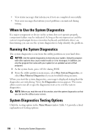
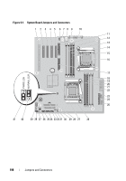
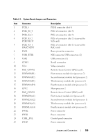
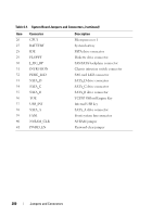
Table 6-1. System Board Jumpers and Connectors Item Connector 1 PCIX_5 2 PCIE_X8_4 3 PCIE_X4_3 4 PCIE_X4_2 PERC SLOT 5 PCIE_X4_1 DRAC SLOT 6 FAN2 7 USB1_ETH1 8 USB2 9 COM1 10 VGA 11 RAC_CONN2 12 DIMM4B (B1) 13 DIMM4A (B2) 14 DIMM3B (B3) 15 DIMM4A (B4) 16 CPU2 17 RAC_CONN1 18 DIMM2B (A1) 19 DIMM2A (A2) 20 DIMM1B (A3) 21 DIMM1A (A4) 22 PWR2 23 PWR1 24 CTRL_PNL 25 PWR3 Description PCI-X connector (slot 5) PCIe x8 connector (slot 4) PCIe x4 connector (slot 3) PCIe x4 connector (slot 2) (reserved for SAS card) PCIe x4 connector (slot 1) (reserved for RAC card) Rear system fan connector NIC connector, USB connectors (2) USB connectors (3) Serial connector Video connector Remote Access Control (RAC) card 2 First memory module slot (processor 2) Second memory module slot (processor 2) Third memory module slot (processor 2) Fourth memory module slot (processor 2) Microprocessor 2 Remote Access Control (RAC) card 1 First memory module slot (processor 1) Second memory module slot (processor 1) Third memory module slot (processor 1) Fourth memory module slot (processor 1) Power connector Power connector Control panel connector Power connector Jumpers and Connectors 199
-
 1
1 -
2
-
3
-
4
-
5
-
6
-
7
-
8
-
9
-
10
-
11
-
12
-
13
-
14
-
15
-
16
-
17
-
18
-
19
-
20
-
21
-
22
-
23
-
24
-
25
-
26
-
27
-
28
-
29
-
30
-
31
-
32
-
33
-
34
-
35
-
36
-
37
-
38
-
39
-
40
-
41
-
42
-
43
-
44
-
45
-
46
-
47
-
48
-
49
-
50
-
51
-
52
-
53
-
54
-
55
-
56
-
57
-
58
-
59
-
60
-
61
-
62
-
63
-
64
-
65
-
66
-
67
-
68
-
69
-
70
-
71
-
72
-
73
-
74
-
75
-
76
-
77
-
78
-
79
-
80
-
81
-
82
-
83
-
84
-
85
-
86
-
87
-
88
-
89
-
90
-
91
-
92
-
93
-
94
-
95
-
96
-
97
-
98
-
99
-
100
-
101
-
102
-
103
-
104
-
105
-
106
-
107
-
108
-
109
-
110
-
111
-
112
-
113
-
114
-
115
-
116
-
117
-
118
-
119
-
120
-
121
-
122
-
123
-
124
-
125
-
126
-
127
-
128
-
129
-
130
-
131
-
132
-
133
-
134
-
135
-
136
-
137
-
138
-
139
-
140
-
141
-
142
-
143
-
144
-
145
-
146
-
147
-
148
-
149
-
150
-
151
-
152
-
153
-
154
-
155
-
156
-
157
-
158
-
159
-
160
-
161
-
162
-
163
-
164
-
165
-
166
-
167
-
168
-
169
-
170
-
171
-
172
-
173
-
174
-
175
-
176
-
177
-
178
-
179
-
180
-
181
-
182
-
183
-
184
-
185
-
186
-
187
-
188
-
189
-
190
-
191
-
192
-
193
-
 194
194 -
 195
195 -
 196
196 -
 197
197 -
 198
198 -
 199
199 -
 200
200 -
 201
201 -
 202
202 -
 203
203 -
 204
204 -
205
-
206
-
207
-
208
-
209
-
210
-
211
-
212
-
213
-
214
-
215
-
216
-
217
-
218
-
219
-
220
-
221
-
222
-
223
-
224
-
225
-
226
-
227
-
228
-
229
-
230
 |
 |