HP Deskjet 320 Solutions Guide - Page 111
Interface Pinout Information, Caution
 |
View all HP Deskjet 320 manuals
Add to My Manuals
Save this manual to your list of manuals |
Page 111 highlights
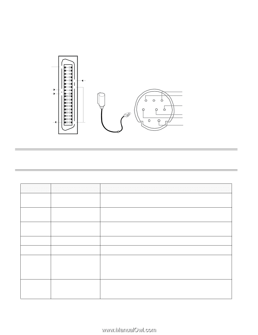
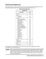
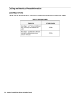
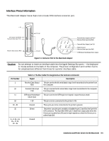
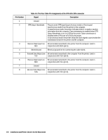
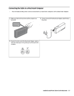
Interface Pinout Information The Macintosh Adapter has an 8-pin mini-circular DIN interface connector port. + 5V 18 DTR Input Handshake Transmit Data Input TXD 32 30 11 10 Driven Receive Data Output RXD 1 19 Ground 6 78 3 45 12 Transmit Data Output Line TxD+ Receive Data Input Line RxD+ Transmit Data Output Line TxDShield Ground Receive Data Input Line RxDDTR Output Handshake/Clock Output Figure 5-1. Connector Port for the Macintosh Adapter Caution Do not attempt to insert an interface cable into the Apple Desktop Bus ports - the keyboard or mouse sockets on the back of the computer. The pinout configuration and number of pins for a keyboard are different from those for a printer interface cable. Pin Number 1 10 11 18 19 - 30 32 2 - 9, 12 - 14, 15 - 17, 31, 33 - 36 Table 5-4. The Mac Cable Pin Assignments at the Centronics Connector Signal Description Receive Data Output RXD This pin carries the bit serial data in logic level transmitted to the printer from the computer. Transmit Data Input TXD This pin carries the bit serial data in logic level transmitted to the computer from the printer. DTR Input Handshake/ This pin carries the DTR logic level signal in asynchronous mode. Clock Input + 5V This pin is to be connected to the printer's +5V. Ground These pins are to be connected to the printer's ground. Driven The printer uses this pin to enable or disable the pin 2, 5and 8 at the 8 pin Mini DIN connector. The 8 pin Mini DIN's pin 2, 5and 8 are output pins when the Driven pin is pulled low (0V) and in high impedence when the Driven pin is pulled high (5V). Unused Installation and Printer Drivers for the Macintosh 5-5
-
 1
1 -
2
-
3
-
4
-
5
-
6
-
7
-
8
-
9
-
10
-
11
-
12
-
13
-
14
-
15
-
16
-
17
-
18
-
19
-
20
-
21
-
22
-
23
-
24
-
25
-
26
-
27
-
28
-
29
-
30
-
31
-
32
-
33
-
34
-
35
-
36
-
37
-
38
-
39
-
40
-
41
-
42
-
43
-
44
-
45
-
46
-
47
-
48
-
49
-
50
-
51
-
52
-
53
-
54
-
55
-
56
-
57
-
58
-
59
-
60
-
61
-
62
-
63
-
64
-
65
-
66
-
67
-
68
-
69
-
70
-
71
-
72
-
73
-
74
-
75
-
76
-
77
-
78
-
79
-
80
-
81
-
82
-
83
-
84
-
85
-
86
-
87
-
88
-
89
-
90
-
91
-
92
-
93
-
94
-
95
-
96
-
97
-
98
-
99
-
100
-
101
-
102
-
103
-
104
-
105
-
 106
106 -
 107
107 -
 108
108 -
 109
109 -
 110
110 -
 111
111 -
 112
112 -
 113
113 -
 114
114 -
 115
115 -
 116
116 -
117
-
118
-
119
-
120
-
121
-
122
-
123
-
124
-
125
-
126
-
127
-
128
-
129
-
130
-
131
-
132
-
133
-
134
-
135
-
136
-
137
-
138
-
139
-
140
-
141
-
142
-
143
-
144
-
145
-
146
-
147
-
148
-
149
-
150
-
151
-
152
-
153
-
154
-
155
-
156
-
157
-
158
-
159
-
160
-
161
-
162
-
163
-
164
-
165
-
166
-
167
-
168
-
169
-
170
-
171
-
172
-
173
-
174
-
175
-
176
-
177
-
178
-
179
-
180
-
181
-
182
-
183
-
184
-
185
-
186
-
187
-
188
-
189
-
190
-
191
-
192
-
193
-
194
-
195
-
196
-
197
-
198
-
199
-
200
-
201
-
202
 |
 |