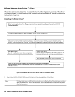
HP Deskjet 320 Solutions Guide - Page 112
Installation and Printer Drivers for the Macintosh, Table 5-5. The Mac Cable Pin Assignments at
 |
View all HP Deskjet 320 manuals
Add to My Manuals
Save this manual to your list of manuals |
Page 112 highlights
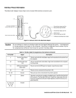
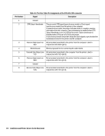
Pin Number 1 2 3 4 5 6 7 8 Table 5-5. The Mac Cable Pin Assignments at the 8 Pin Mini DIN connector Signal Description Unused DTR Output Handshake This pin sends DTR signal (asynchronous mode) or Clock signal (synchronous mode) from the printer to the computer. In asynchronous mode, the printer indicates when it is ready to receive information from the computer. Data transmission is enabled when DTR Output Handshake is set on (+5V) by the printer. Data transmission is disabled when DTR is set off (-5V) by the printer. In synchronous mode, the printer sends the Clock signal to synchronise the transmission between the printer and the computer. Receive Data Input Line Bit serial data transmitted to the printer from the computer. Used in RxD- conjunction with RxD+ (pin 6) Shield Ground Electrical ground line for connecting the cable shield. Transmit Data Output Line Bit serial data transmitted to the computer from the printer. Used in TxD- conjunction with TxD+ (pin 8). Receive Data Input Line Bit serial data transmitted to the printer from the computer. Used in RxD+ conjunction with TxD- (pin 3). Unused Receive Data Output Line Bit serial data transmitted to the printer from the computer. Used in TxD+ conjunction with TxD- (pin 5). 5-6 Installation and Printer Drivers for the Macintosh
-
 1
1 -
2
-
3
-
4
-
5
-
6
-
7
-
8
-
9
-
10
-
11
-
12
-
13
-
14
-
15
-
16
-
17
-
18
-
19
-
20
-
21
-
22
-
23
-
24
-
25
-
26
-
27
-
28
-
29
-
30
-
31
-
32
-
33
-
34
-
35
-
36
-
37
-
38
-
39
-
40
-
41
-
42
-
43
-
44
-
45
-
46
-
47
-
48
-
49
-
50
-
51
-
52
-
53
-
54
-
55
-
56
-
57
-
58
-
59
-
60
-
61
-
62
-
63
-
64
-
65
-
66
-
67
-
68
-
69
-
70
-
71
-
72
-
73
-
74
-
75
-
76
-
77
-
78
-
79
-
80
-
81
-
82
-
83
-
84
-
85
-
86
-
87
-
88
-
89
-
90
-
91
-
92
-
93
-
94
-
95
-
96
-
97
-
98
-
99
-
100
-
101
-
102
-
103
-
104
-
105
-
106
-
 107
107 -
 108
108 -
 109
109 -
 110
110 -
 111
111 -
 112
112 -
 113
113 -
 114
114 -
 115
115 -
 116
116 -
 117
117 -
118
-
119
-
120
-
121
-
122
-
123
-
124
-
125
-
126
-
127
-
128
-
129
-
130
-
131
-
132
-
133
-
134
-
135
-
136
-
137
-
138
-
139
-
140
-
141
-
142
-
143
-
144
-
145
-
146
-
147
-
148
-
149
-
150
-
151
-
152
-
153
-
154
-
155
-
156
-
157
-
158
-
159
-
160
-
161
-
162
-
163
-
164
-
165
-
166
-
167
-
168
-
169
-
170
-
171
-
172
-
173
-
174
-
175
-
176
-
177
-
178
-
179
-
180
-
181
-
182
-
183
-
184
-
185
-
186
-
187
-
188
-
189
-
190
-
191
-
192
-
193
-
194
-
195
-
196
-
197
-
198
-
199
-
200
-
201
-
202
 |
 |