Brother International PEDESIGN 8.0 Users Manual - English - Page 163
Drawing a broken line, Changing application, settings, Viewing outlines in the, Reference Window
 |
View all Brother International PEDESIGN 8.0 manuals
Add to My Manuals
Save this manual to your list of manuals |
Page 163 highlights
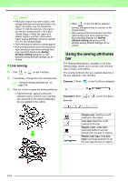
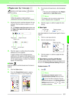
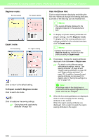
Manually Creating Embroidery Patterns From Images (Design Center) Drawing a broken line The line drawing mode allows you to add broken lines to your pattern. A broken line is made of one or more adjacent straight lines, in other words, the end point of one straight line is the start point of the next one. If the broken line that you drew did not create enclosed regions, it remains a simple outline, and you can only set sewing attributes for the line itself in the Sew Setting Stage. If the broken line created enclosed regions, you can assign sew types and colors to both the outline and the regions in the Sew Setting Stage. If you draw a line through an existing region, creating two separate regions, you will be able to set sewing attributes for both regions separately, as well as for the separating line. End point Start point Broken line without a region Broken line with region Broken lines with two regions For details on drawing lines, refer to "Adding lines to the figure handle image" on page 148. Changing application settings ■ Changing the grid settings A grid of dotted lines or solid lines can be displayed or hidden, and the spacing for the grid can be adjusted. (This function is available only in the Figure Handle Stage.) 1. Click Display, then Grid Setup. 2. To display the grid, select the Show Grid check box. To hide the grid, clear the Show Grid check box. 3. To set the grid spacing, type or select a value in the Grid interval box. 4. To display the grid as solid lines, select the with Axes check box. To display the grid as dots (intersecting points of the grid) , clear the with Axes check box. 5. Click OK to apply the changes and to close the dialog box. ■ Changing the measurement units The measurements for values displayed in the application can be in either millimeters or inches. 1. Click Option, then Select System Unit, and then select the desired measurement units (mm or inch). Viewing outlines in the Reference Window All outlines in the Design Page are displayed in the Reference Window, giving you an overall view of the outline while you work on a detailed area. The display area frame (red rectangle) indicates the part of the outline displayed in the Design Page. In addition, the image being used to create the embroidery pattern or the embroidery pattern being created and a different image can be displayed in the Reference Window in the Figure Handle Stage and the Sew Setting Stage. To switch between displaying and hiding the Reference window, click Display, then Reference Window, or click , or press the shortcut key ( F11 ). Manually Creating Embroidery Patterns From Images (Design Center) 161
-
 1
1 -
2
-
3
-
4
-
5
-
6
-
7
-
8
-
9
-
10
-
11
-
12
-
13
-
14
-
15
-
16
-
17
-
18
-
19
-
20
-
21
-
22
-
23
-
24
-
25
-
26
-
27
-
28
-
29
-
30
-
31
-
32
-
33
-
34
-
35
-
36
-
37
-
38
-
39
-
40
-
41
-
42
-
43
-
44
-
45
-
46
-
47
-
48
-
49
-
50
-
51
-
52
-
53
-
54
-
55
-
56
-
57
-
58
-
59
-
60
-
61
-
62
-
63
-
64
-
65
-
66
-
67
-
68
-
69
-
70
-
71
-
72
-
73
-
74
-
75
-
76
-
77
-
78
-
79
-
80
-
81
-
82
-
83
-
84
-
85
-
86
-
87
-
88
-
89
-
90
-
91
-
92
-
93
-
94
-
95
-
96
-
97
-
98
-
99
-
100
-
101
-
102
-
103
-
104
-
105
-
106
-
107
-
108
-
109
-
110
-
111
-
112
-
113
-
114
-
115
-
116
-
117
-
118
-
119
-
120
-
121
-
122
-
123
-
124
-
125
-
126
-
127
-
128
-
129
-
130
-
131
-
132
-
133
-
134
-
135
-
136
-
137
-
138
-
139
-
140
-
141
-
142
-
143
-
144
-
145
-
146
-
147
-
148
-
149
-
150
-
151
-
152
-
153
-
154
-
155
-
156
-
157
-
 158
158 -
 159
159 -
 160
160 -
 161
161 -
 162
162 -
 163
163 -
 164
164 -
 165
165 -
 166
166 -
 167
167 -
 168
168 -
169
-
170
-
171
-
172
-
173
-
174
-
175
-
176
-
177
-
178
-
179
-
180
-
181
-
182
-
183
-
184
-
185
-
186
-
187
-
188
-
189
-
190
-
191
-
192
-
193
-
194
-
195
-
196
-
197
-
198
-
199
-
200
-
201
-
202
-
203
-
204
-
205
-
206
-
207
-
208
-
209
-
210
-
211
-
212
-
213
-
214
-
215
-
216
-
217
-
218
-
219
-
220
-
221
-
222
-
223
-
224
-
225
-
226
-
227
-
228
-
229
-
230
-
231
-
232
-
233
-
234
-
235
-
236
-
237
-
238
-
239
-
240
-
241
-
242
-
243
-
244
-
245
-
246
-
247
-
248
-
249
-
250
-
251
-
252
-
253
-
254
-
255
-
256
-
257
-
258
-
259
-
260
-
261
-
262
-
263
-
264
-
265
-
266
-
267
-
268
-
269
 |
 |
