Netgear GS752TS GS7xxTS-TPS Software Admin Manual
Netgear GS752TS Manual
 |
View all Netgear GS752TS manuals
Add to My Manuals
Save this manual to your list of manuals |
Netgear GS752TS manual content summary:
- Netgear GS752TS | GS7xxTS-TPS Software Admin Manual - Page 1
GS728TS, GS728TPS, GS752TS, and GS752TPS Gigabit Smart Switches Software Administration Manual 350 East Plumeria Drive San Jose, CA 95134 USA February 2012 202-10995-01 v1.0 - Netgear GS752TS | GS7xxTS-TPS Software Admin Manual - Page 2
GS728TS, GS728TPS, GS752TS, and GS752TPS Gigabit Smart Switches ©2012 NETGEAR, Inc. All rights reserved No updates, get support online, or for more information about the topics covered in this manual, visit the Support website at http://support.netgear.com Phone (US & Canada only): 1-888-NETGEAR - Netgear GS752TS | GS7xxTS-TPS Software Admin Manual - Page 3
33 IP Configuration 35 IPv6 Network Configuration 37 IPv6 Network Neighbor 38 Time 40 Denial of Service 45 DNS 49 Green Ethernet 51 Stacking 61 Stack Features 61 Firmware Synchronization and Upgrade 62 Configuration Maintenance 62 Stack Master Election 62 Factory Defaults Reset Behavior - Netgear GS752TS | GS7xxTS-TPS Software Admin Manual - Page 4
GS728TS, GS728TPS, GS752TS, and GS752TPS Gigabit Smart Switches PoE/PoE+ (GS728TPS and GS752TPS Only 70 PoE Configuration 70 PoE Port Configuration 72 SNMP 75 SNMPv1/v2 75 Trap Configuration 77 Trap Flags 78 SNMP Supported MIBs 79 SNMP v3 User Configuration 79 LLDP 80 LLDP Configuration - Netgear GS752TS | GS7xxTS-TPS Software Admin Manual - Page 5
GS728TS, GS728TPS, GS752TS, and GS752TPS Gigabit Smart Switches Spanning Tree Protocol 122 STP Switch Configuration 123 CST Configuration 125 CST Port Configuration 126 CST Port Status 128 Rapid STP 129 MST Configuration 130 MST Port Configuration 131 STP Statistics 134 Multicast 135 MFDB - Netgear GS752TS | GS7xxTS-TPS Software Admin Manual - Page 6
GS728TS, GS728TPS, GS752TS, and GS752TPS Gigabit Smart Switches IPv6 Class Configuration 189 Policy Configuration 191 Service Configuration 195 Service Statistics 196 Chapter 6 Managing Device Security Management Security Settings 197 Change Password 198 RADIUS Configuration 199 Configuring - Netgear GS752TS | GS7xxTS-TPS Software Admin Manual - Page 7
Status 291 Troubleshooting 292 Ping 292 Ping IPv6 293 Traceroute 294 Chapter 9 Accessing Help Online Help 296 Support 296 User Guide 297 Registration 298 Appendix A Hardware Specifications and Default Values Switch Specifications 300 GS728TS Specifications 300 GS728TPS Specifications 300 - Netgear GS752TS | GS7xxTS-TPS Software Admin Manual - Page 8
GS728TS, GS728TPS, GS752TS, and GS752TPS Gigabit Smart Switches Switch Features and Defaults 302 Traffic Control 302 Quality of Service 303 Security 303 System Setup and Maintenance 304 System Management 304 Other Features 305 Appendix B Configuration Examples Virtual Local Area Networks ( - Netgear GS752TS | GS7xxTS-TPS Software Admin Manual - Page 9
Started 1 The NETGEAR®GS728TS, GS728TPS, GS752TS, and GS752TPS Smart Switch Software Administration Manual describes how to configure and operate the GS728TS, GS728TPS, GS752TS, and GS752TPS Gigabit Smart Switches by using the Web-based graphical user interface (GUI). This manual describes the - Netgear GS752TS | GS7xxTS-TPS Software Admin Manual - Page 10
14 • Configuring the Network Settings on the Administrative System on page 15 • Web Access on page 16 • Smart Control Center Utilities on page 17 • Understanding the User Interfaces on page 23 • Interface Naming Convention on page 30 Switch Management Interface The NETGEAR GS728TS, GS728TPS, GS752TS - Netgear GS752TS | GS7xxTS-TPS Software Admin Manual - Page 11
through a Web browser or SNMP, you must connect the switch to the network and configure it with network information (an IP address, subnet mask, and default gateway). The switch has a default IP address of 192.168.0.239 and a default subnet mask of 255.255.255.0. Use one of the following three - Netgear GS752TS | GS7xxTS-TPS Software Admin Manual - Page 12
DHCP client on the switch is enabled by default. When you connect it to your network, the DHCP server will automatically assign an IP address to your switch. Use the Smart Control Center to discover the IP address automatically assigned to the switch. To install the switch in a network with a DHCP - Netgear GS752TS | GS7xxTS-TPS Software Admin Manual - Page 13
GS728TS, GS728TPS, GS752TS, and GS752TPS Gigabit Smart Switches 6. Make a note of the displayed IP address assigned by the DHCP server. You will need this value to access the switch directly from a Web browser (without using the Smart Control Center). 7. Select your switch by clicking the line that - Netgear GS752TS | GS7xxTS-TPS Software Admin Manual - Page 14
IP address: 1. Connect the switch to your existing network. 2. Power on the switch by plugging in the AC-DC power adapter. 3. Install the Smart Control Center on your computer. 4. Start the Smart Control Center. 5. Click Discover for the Smart Control Center to find your GS728TS, GS728TPS, GS752TS - Netgear GS752TS | GS7xxTS-TPS Software Admin Manual - Page 15
DHCP. 8. Enter the static switch IP address, gateway IP address and subnet mask, and then type your password and click Apply. Tip: You must enter the current password every time you use the Smart Control Center to update the switch setting. The default password is password. Please ensure that your - Netgear GS752TS | GS7xxTS-TPS Software Admin Manual - Page 16
.0.200. The IP address must be different from that of the switch but within the same subnet. 3. Click OK. To configure a static address on the switch: 1. Use a straight-through cable to connect the Ethernet port on the administrative system directly to any port on the GS728TS, GS728TPS, GS752TS, or - Netgear GS752TS | GS7xxTS-TPS Software Admin Manual - Page 17
-Allows you to modify network information for the switch, including the IP address, DHCP client mode, system name, and location. For more information about this feature, see Configuring the Device. • Change Password-Allows you to set a new password for the device. For more information about this - Netgear GS752TS | GS7xxTS-TPS Software Admin Manual - Page 18
GS728TS, GS728TPS, GS752TS, and GS752TPS Gigabit Smart Switches Configuring the Device To modify switch information: 1. Select the switch. 2. Click Configure Device. Additional fields appear on the screen. 3. To assign or update a static IP address, default gateway, or subnet mask, disable the DHCP - Netgear GS752TS | GS7xxTS-TPS Software Admin Manual - Page 19
GS728TS, GS728TPS, GS752TS, and GS752TPS Gigabit Smart Switches Configuration Upload and Download When you make changes to the switch, the configuration information is stored in a file on the switch. You can backup the configuration by uploading the configuration file from the switch to an - Netgear GS752TS | GS7xxTS-TPS Software Admin Manual - Page 20
: Click the Tasks tab to view status information about the configuration download. Firmware Upgrade The application software for the GS728TS, GS728TPS, GS752TS, and GS752TPS Smart Switches is upgradeable, enabling your switch to take advantage of improvements and additional features as they become - Netgear GS752TS | GS7xxTS-TPS Software Admin Manual - Page 21
GS728TS, GS728TPS, GS752TS, and GS752TPS Gigabit Smart Switches By default, the firmware is downloaded to primary storage and will be become the active image after the download completes and the switch reboots. To download firmware to use as a backup image, select the Secondary Storage option. To - Netgear GS752TS | GS7xxTS-TPS Software Admin Manual - Page 22
GS728TS, GS728TPS, GS752TS, and GS752TPS Gigabit Smart Switches WARNING: It is important that you do not power-off the administrative system or the switch while the firmware upgrade is in progress. Viewing and Managing Tasks From the Tasks tab, you can view information about configuration downloads - Netgear GS752TS | GS7xxTS-TPS Software Admin Manual - Page 23
allows you to configure and monitor the components of the GS728TS, GS728TPS, GS752TS, and GS752TPS switches software. The method enter the IP address of the switch in the Web browser address field. 2. The factory default password is password. Type the password into the field on the login screen, as - Netgear GS752TS | GS7xxTS-TPS Software Admin Manual - Page 24
GS728TS, GS728TPS, GS752TS, and GS752TPS Gigabit Smart Switches Navigation Tab Feature Link Help Link Logout Button Help Page Page Menu Configuration Status and Options Figure 3. Administrative Page Layout Navigation Tabs, Feature Links, and Page Menu The navigation tabs along the top of the - Netgear GS752TS | GS7xxTS-TPS Software Admin Manual - Page 25
Function Clicking Add adds the new item configured in the heading row of a table. Clicking the Apply button sends the updated configuration to the switch. Configuration changes take effect immediately. Clicking Cancel cancels the configuration on the screen and resets the data on the screen to the - Netgear GS752TS | GS7xxTS-TPS Software Admin Manual - Page 26
GS728TS, GS728TPS, GS752TS, and GS752TPS Gigabit Smart Switches Device View The Device View is a Java® applet that displays the ports on the switch. This graphic provides an alternate way to navigate to configuration 1 Gbps or 2.5 Gbps (if used for stacking) link speed. • A yellow LED indicates - Netgear GS752TS | GS7xxTS-TPS Software Admin Manual - Page 27
Smart Switches The following figure shows the Device View of the GS728TS. The following figure shows the Device View of the GS728TPS. The following figure shows the Device View of the GS752TS. The following figure shows the Device View of the GS752TPS. Click the port you want to view or configure to - Netgear GS752TS | GS7xxTS-TPS Software Admin Manual - Page 28
GS728TS, GS728TPS, GS752TS, and GS752TPS Gigabit Smart Switches If you click the graphic, but do not click a specific port, the main menu appears, as the following figure shows. This menu contains the same option as the navigation tabs at the top of the page. 28 - Netgear GS752TS | GS7xxTS-TPS Software Admin Manual - Page 29
Web page. All characters may be used except for the following (unless specifically noted in for that feature): \ < / >| * | ? Using SNMP The GS728TS, GS728TPS, GS752TS, and GS752TPS switches software supports the configuration of SNMP groups and users that can manage traps that the SNMP - Netgear GS752TS | GS7xxTS-TPS Software Admin Manual - Page 30
Naming Convention The GS728TS, GS728TPS, GS752TS, and GS752TPS switches software supports physical and logical interfaces. Interfaces are identified by their type and the interface number. The physical ports are gigabit interfaces and are numbered on the front panel. You can configure the logical - Netgear GS752TS | GS7xxTS-TPS Software Admin Manual - Page 31
2. Configuring System Information 2 Use the features in the System tab to define the switch's relationship to its environment. The System tab contains links to the following features: • Management on page 31 • Stacking on page 61 • PoE/PoE+ (GS728TPS and GS752TPS Only) on page 70 • SNMP on page 75 - Netgear GS752TS | GS7xxTS-TPS Software Admin Manual - Page 32
GS728TS, GS728TPS, GS752TS, and GS752TPS Gigabit Smart Switches System Information After a successful login, the System Information page displays. Use this page to configure and view general device information. To display the System Information page, click System > Management > System Information. A - Netgear GS752TS | GS7xxTS-TPS Software Admin Manual - Page 33
GS728TS, GS728TPS, GS752TS, and GS752TPS Gigabit Smart Switches Field Date & Time System Up Time Base MAC Address Fan Status Table Unit the different units in the stack. The page also displays information about the card types and switch models supported in the stack. To display the Slot Information - Netgear GS752TS | GS7xxTS-TPS Software Admin Manual - Page 34
GS728TS, GS728TPS, GS752TS, and GS752TPS Gigabit Smart Switches Click Refresh to refresh the screen with most recent data. The following table describes the status information the Slot Information displays. Field Slot Summary Slot Status Administrative State Power State Configured Card Model ID - Netgear GS752TS | GS7xxTS-TPS Software Admin Manual - Page 35
that the switch must obtain the IP address through a DHCP server. • Dynamic IP Address (BOOTP). Specifies that the switch must obtain the IP address through a BootP server. • Static IP Address. Specifies that the IP address, subnet mask, and default gateway must be manually configured. Enter this - Netgear GS752TS | GS7xxTS-TPS Software Admin Manual - Page 36
GS728TS, GS728TPS, GS752TS, and GS752TPS Gigabit Smart Switches 3. Specify the VLAN ID for the management VLAN. The management VLAN is used to establish an IP connection to the switch the management VLAN ID. For information about creating VLANs and configuring the PVID for a port, see VLANs on page - Netgear GS752TS | GS7xxTS-TPS Software Admin Manual - Page 37
GS728TS, GS728TPS, GS752TS, and GS752TPS Gigabit Smart Switches IPv6 Network Configuration Use the IPv6 Network Configuration page to configure the IPv6 network interface, which is the logical interface used for in-band connectivity with the switch via all of the switch's front-panel ports. The - Netgear GS752TS | GS7xxTS-TPS Software Admin Manual - Page 38
GS728TS, GS728TPS, GS752TS, and GS752TPS Gigabit Smart Switches To configure the network information for an IPv6 network: 1. Admin Mode. Enable or disable the IPv6 network interface on the switch. The default value is Enable. 2. IPv6 Address Auto Configuration Mode. The IPv6 address for the IPv6 - Netgear GS752TS | GS7xxTS-TPS Software Admin Manual - Page 39
Neighbor Table displays Field IPv6 Address MAC Address IsRtr Neighbor State Last Updated. Description Specifies the IPv6 address of neighbor or interface. Specifies MAC address associated with an interface. Indicates whether the neighbor is a router. If the neighbor is a router, the value is True - Netgear GS752TS | GS7xxTS-TPS Software Admin Manual - Page 40
Switches Time The GS728TS, GS728TPS, GS752TS, and GS752TPS switch software supports the Simple Network Time Protocol (SNTP). You can also set the system time manually used for polling a server for which the IP address is known. SNTP servers that have been configured on the device are the only ones - Netgear GS752TS | GS7xxTS-TPS Software Admin Manual - Page 41
GS728TS, GS728TPS, GS752TS, and GS752TPS Gigabit Smart Switches Time Configuration Use the Time Configuration page to view and adjust date and time settings. To display the Time Configuration page, click System > Management > Time > SNTP Global Configuration. To configure the time by using the CPU - Netgear GS752TS | GS7xxTS-TPS Software Admin Manual - Page 42
switch. The SNTP Global Status table on the Time Configuration page displays information about the system's SNTP client. The following table describes the SNTP Global Status fields. Field Version Supported Mode Last Update Time Last Attempt Time Last Attempt Status Server IP Address Description - Netgear GS752TS | GS7xxTS-TPS Software Admin Manual - Page 43
GS728TS, GS728TPS, GS752TS, and GS752TPS Gigabit Smart Switches Field Description Address Type Specifies the address type of the SNTP Server address with the most current data from the switch. SNTP Server Configuration Use the SNTP Server Configuration page to view and modify information for - Netgear GS752TS | GS7xxTS-TPS Software Admin Manual - Page 44
GS728TS, GS728TPS, GS752TS, and GS752TPS Gigabit Smart Switches To configure a new SNTP Server: 1. Enter the appropriate SNTP server information in the available fields: • Server Type. Specifies whether the address for the SNTP server is an IP address (IPv4) or hostname (DNS). • Address. Enter the - Netgear GS752TS | GS7xxTS-TPS Software Admin Manual - Page 45
SNTP operation was successful and the system time was updated. • Request Timed Out: A directed SNTP switch. Denial of Service Use the Denial of Service (DoS) page to configure DoS control. The GS728TS, GS728TPS, GS752TS, and GS752TPS switches provide support for classifying and blocking specific - Netgear GS752TS | GS7xxTS-TPS Software Admin Manual - Page 46
Auto-DoS: • Disable. Auto-DoS is disabled (default). • Enable. Auto-DoS is enabled. 2. Click Apply to send the updated configuration to the switch. Configuration changes occur immediately. 3. Click Cancel to cancel the configuration on the screen and reset the data on the screen to the latest value - Netgear GS752TS | GS7xxTS-TPS Software Admin Manual - Page 47
GS728TS, GS728TPS, GS752TS, and GS752TPS Gigabit Smart Switches DoS Configuration The DoS Configuration page lets you to select which types of DoS attacks for the switch to monitor and block. To access the DoS Configuration page, click System > Management > Denial of Service > Denial of Service - Netgear GS752TS | GS7xxTS-TPS Software Admin Manual - Page 48
selecting the appropriate radio button. Enabling SIP=DIP DoS prevention causes the switch to drop packets that have a source IP address equal to the destination IP address. The factory default is Disable. • Denial of Service SMAC=DMAC. Enable or disable this option by selecting the appropriate radio - Netgear GS752TS | GS7xxTS-TPS Software Admin Manual - Page 49
that have UDP source port equal to UDP destination port. The factory default is disabled. 2. If you change any of the DoS settings, click Apply to apply the changes to the switch. 3. Click Cancel to cancel the configuration on the screen and reset the data on the screen to the latest value of the - Netgear GS752TS | GS7xxTS-TPS Software Admin Manual - Page 50
cancel the configuration on the screen and reset the data on the screen to the latest value of the switch. 6. Click Apply to send the updated configuration to the switch. Configuration changes take effect immediately. Host Configuration Use this page to manually map host names to IP addresses or to - Netgear GS752TS | GS7xxTS-TPS Software Admin Manual - Page 51
, and then click Apply. 6. Click Cancel to cancel the configuration on the screen and reset the data on the screen to the latest value of the switch. The Dynamic Host Configuration table shows host name-to-IP address entries that the switch has learned. The following table describes the dynamic host - Netgear GS752TS | GS7xxTS-TPS Software Admin Manual - Page 52
GS728TS, GS728TPS, GS752TS, and GS752TPS Gigabit Smart Switches To configure the Green Ethernet feature: 1. Enable or disable the Auto Power-Down Mode. • Enable. When the port link is down, the PHY automatically goes down for a - Netgear GS752TS | GS7xxTS-TPS Software Admin Manual - Page 53
GS728TS, GS728TPS, GS752TS, and GS752TPS Gigabit Smart Switches Green Ethernet Interface Configuration Use this page to configure Green Ethernet features on a per-port basis. The Green Ethernet modes must be administratively enabled on the switch for the mode enabled on the port to take effect. To - Netgear GS752TS | GS7xxTS-TPS Software Admin Manual - Page 54
immediately. 6. Click Cancel to cancel the configuration on the screen and reset the data on the screen to the latest value of the switch. Green Ethernet Detail Use this page to configure Green Ethernet monitor and manage Green Ethernet features on a specific port. To access this page, click System - Netgear GS752TS | GS7xxTS-TPS Software Admin Manual - Page 55
GS728TS, GS728TPS, GS752TS, and GS752TPS Gigabit Smart Switches To configure or view details about the Green Ethernet feature on a port: 1. Within the Local Device Information, select the port to view or configure of Tw_sys that the local system can support. Tw_sys_tx Echo (uSec) Integer that - Netgear GS752TS | GS7xxTS-TPS Software Admin Manual - Page 56
GS728TS, GS728TPS, GS752TS, and GS752TPS Gigabit Smart Switches Field Description Tx_dll_ready Data Link Layer ready: This variable indicates that the tx system initialization is complete and is ready to update reset the counters on the page to their default values. 7. Click Refresh to update the - Netgear GS752TS | GS7xxTS-TPS Software Admin Manual - Page 57
GS728TS, GS728TPS, GS752TS, and GS752TPS Gigabit Smart Switches Green Ethernet Summary This page summarizes the Green Ethernet Summary stack in mWatts. by all ports in Stack (mWatts) Estimated Percentage Estimated Percentage Power saved on all ports in the stack due to Green Power Saving per stack - Netgear GS752TS | GS7xxTS-TPS Software Admin Manual - Page 58
GS728TS, GS728TPS, GS752TS, and GS752TPS Gigabit Smart Switches Field Description Unit Identifies the stack member number. Green Features supported on this unit List of Green Features supported idle condition. Click Refresh to update the page with the most current data from the switch 58 - Netgear GS752TS | GS7xxTS-TPS Software Admin Manual - Page 59
GS728TS, GS728TPS, GS752TS, and GS752TPS Gigabit Smart Switches Green Ethernet LPI History Use this LPI samples to store on the switch. The default is 168, and the range is 1 to 168. 3. Click Apply to send the updated configuration to the switch. Configuration changes take effect immediately. 4. - Netgear GS752TS | GS7xxTS-TPS Software Admin Manual - Page 60
GS728TS, GS728TPS, GS752TS, and GS752TPS Gigabit Smart Switches The page also provides the information shown in the following table: Field Description Percentage LPI time per Stack Time spent in LPI mode since EEE LPI mode since EEE LPI statistics were last LPI mode since last reset reset. 60 - Netgear GS752TS | GS7xxTS-TPS Software Admin Manual - Page 61
Stacking on the GS728TS, GS728TPS, GS752TS, and GS752TPS switches supports the following: • Up to six switches per stack, which can be any combination of GS728TS, GS728TPS, GS752TS, or GS752TPS switches. • Single IP address management through a web browser or the SCC. • Master-slave configuration - Netgear GS752TS | GS7xxTS-TPS Software Admin Manual - Page 62
GS728TS, GS728TPS, GS752TS, and GS752TPS Gigabit Smart Switches Firmware Synchronization and Upgrade All stack members must run the same software version to ensure compatibility within the stack. By default, if a unit is added to the stack and its software version is not the same as the stack master - Netgear GS752TS | GS7xxTS-TPS Software Admin Manual - Page 63
is reset to the factory default settings (see Factory Default on page 281), the stack master applies the default settings to all the stack members and resets the stack, including all participating stack members. When the stack boots, the stack master election process begins. Stack Configuration From - Netgear GS752TS | GS7xxTS-TPS Software Admin Manual - Page 64
GS728TS, GS728TPS, GS752TS, and GS752TPS Gigabit Smart Switches To select a new stack master: 1. In the Management Unit Selected menu, select the unit ID of the stack member to become the stack master. 2. A message indicating that moving stack management will unconfigure entire stack including all - Netgear GS752TS | GS7xxTS-TPS Software Admin Manual - Page 65
Cancel to retain the original settings. 5. Click Delete to remove the selected unit from the stack. 6. Click Refresh to update the page with the latest information from the switch. 7. Click Cancel to cancel the configuration on the screen and reset the data on the screen to the latest value of the - Netgear GS752TS | GS7xxTS-TPS Software Admin Manual - Page 66
stored in flash. This displays the status of last tried stack firmware synchronisation. "None" is the default value if SFS has not been tried. Stack Port Configuration By default, the stack ports on each switch are configured for stacking. However, you can use these ports as standard Ethernet ports - Netgear GS752TS | GS7xxTS-TPS Software Admin Manual - Page 67
GS728TS, GS728TPS, GS752TS, and GS752TPS Gigabit Smart Switches To configure the mode of the stack ports: 1. Select the check box associated with the unit and port to configure: 2. From the Configured Stack Mode field, select the operating mode: • Stack. The port connects to the stack port on - Netgear GS752TS | GS7xxTS-TPS Software Admin Manual - Page 68
GS728TS, GS728TPS, GS752TS, and GS752TPS Gigabit Smart Switches Stack Port Diagnostics This page displays the diagnostics for all the stackable interfaces in the given stack. To display the Stack Port Diagnostics page, click System Stacking Advanced Stack Port Diagnostics. A screen similar to - Netgear GS752TS | GS7xxTS-TPS Software Admin Manual - Page 69
GS728TS, GS728TPS, GS752TS, and GS752TPS Gigabit Smart Switches Stack Firmware Synchronization To display the stack firmware synchronization configurations from the Stack Firmware Synchronization page, click System Stacking Advanced Stack Firmware Synchronization. A screen similar to the - Netgear GS752TS | GS7xxTS-TPS Software Admin Manual - Page 70
GS728TS, GS728TPS, GS752TS, and GS752TPS Gigabit Smart Switches PoE/PoE+ (GS728TPS and GS752TPS Only) Ports g1-g8 on the GS728TPS and GS752TPS are PoE+ (IEEE 802.3at) compliant ports. Each port is capable of delivering up to 30W of reliable, uninterrupted power to connected PoE-powered devices (PD). - Netgear GS752TS | GS7xxTS-TPS Software Admin Manual - Page 71
GS728TS, GS728TPS, GS752TS, and GS752TPS Gigabit Smart Switches To configure PoE trap settings: 1. If you are managing a stack of switches, select the ID of the stack member to configure from the Unit menu. 2. Specify the percentage of the threshold power that must be consumed before a trap is sent - Netgear GS752TS | GS7xxTS-TPS Software Admin Manual - Page 72
GS728TS, GS728TPS, GS752TS, and GS752TPS Gigabit Smart Switches PoE Port Configuration Use the PoE Port Configuration page to configure per-port PoE settings. To display the PoE Port Configuration page, click System > PoE > Advanced > PoE Port Configuration. To configure PoE Port settings: 1. Select - Netgear GS752TS | GS7xxTS-TPS Software Admin Manual - Page 73
GS728TS, GS728TPS, GS752TS, and GS752TPS Gigabit Smart Switches • High Power Mode. Select the power-up mode for the port • Disable: A port is powered in the IEEE 802.3af mode. (Default this value is selected, the user-configured value configured in the Power Limit field is ignored. • User: Select - Netgear GS752TS | GS7xxTS-TPS Software Admin Manual - Page 74
GS728TS, GS728TPS, GS752TS, and GS752TPS Gigabit Smart Switches • Status. View the operational status of the port PD detection. • Disabled. Indicates no power is being delivered. • DeliveringPower. Indicates power is being drawn by a connected device. • Fault. Indicates a problem with the port. • - Netgear GS752TS | GS7xxTS-TPS Software Admin Manual - Page 75
GS728TS, GS728TPS, GS752TS, and GS752TPS Gigabit Smart Switches SNMP From SNMP link under the System tab, you can configure SNMP settings for SNMPv1/v2 and SNMPv3. From the SNMP link, you can access the following pages: • SNMPv1/v2 on page 75 • Trap Flags on page 78 • SNMP v3 User Configuration on - Netgear GS752TS | GS7xxTS-TPS Software Admin Manual - Page 76
GS728TS, GS728TPS, GS752TS, and GS752TPS Gigabit Smart Switches To configure SNMP communities: 1. To add a new SNMP community, enter community information in the available fields described below, and then click Add. • Management Station IP. Specify the IP address of the management station.Together, - Netgear GS752TS | GS7xxTS-TPS Software Admin Manual - Page 77
GS728TS, GS728TPS, GS752TS, and GS752TPS Gigabit Smart Switches Trap Configuration This page displays an entry for every active Trap Receiver. To access this page, click System > SNMP > SNMP V1/V2 > Trap Configuration. To configure SNMP trap settings: 1. To add a host that will receive SNMP traps, - Netgear GS752TS | GS7xxTS-TPS Software Admin Manual - Page 78
. The factory default is Enable. 4. For the GS728TPS and GS752TPS switches, use the PoE field to enable or disable activation of PoE traps. The factory default is Enable. 5. If you make any changes to this page, click Apply to send the updated configuration to the switch. Configuration changes take - Netgear GS752TS | GS7xxTS-TPS Software Admin Manual - Page 79
GS728TS, GS728TPS, GS752TS, and GS752TPS Gigabit Smart Switches SNMP Supported MIBs The SNMP Supported MIBs page lists the MIBs available for management by using a SNMP-based network management system. To access the page, click System > SNMP > SNMP V1/V2 > Supported MIBs. The page displays the name - Netgear GS752TS | GS7xxTS-TPS Software Admin Manual - Page 80
: The user login password will be used as SNMPv3 authentication password, and you must therefore specify a password. The password must be eight updated configuration to the switch. Configuration changes take effect immediately. 5. Click Cancel to cancel the configuration on the screen and reset the - Netgear GS752TS | GS7xxTS-TPS Software Admin Manual - Page 81
GS728TS, GS728TPS, GS752TS, and GS752TPS Gigabit Smart Switches ports. The application is responsible for starting each transmit and receive state machine appropriately, based on the configured status and operational state of the port. The Link Layer Discovery Protocol-Media Endpoint Discovery (LLDP - Netgear GS752TS | GS7xxTS-TPS Software Admin Manual - Page 82
to cancel the configuration on the screen and reset the data on the screen to the latest value of the switch. 5. Click Refresh to update the screen with the current information. LLDP Port Settings Use the LLDP Port Settings page to specify LLDP parameters that are applied to a specific interface. To - Netgear GS752TS | GS7xxTS-TPS Software Admin Manual - Page 83
GS728TS, GS728TPS, GS752TS, and GS752TPS Gigabit Smart Switches To configure LLDP port settings: 1. Change the LLDP port is the default value. • Disabled: Do not transmit or receive LLDP PDUs on the selected ports. • Management IP Address. Choose whether to advertise the management IP address from - Netgear GS752TS | GS7xxTS-TPS Software Admin Manual - Page 84
GS728TS, GS728TPS, GS752TS, and GS752TPS Gigabit Smart Switches From the switch. Specifies the policy number. Specifies the media application type associated with the policy. Only the Voice application type is supported. The Refresh to update the page with the most current data from the switch. 84 - Netgear GS752TS | GS7xxTS-TPS Software Admin Manual - Page 85
MDI: PSE • Extended Power via MDI: PD • Inventory 5. Click Apply to send the updated configuration to the switch. These changes occur immediately and the configuration will be saved. 6. Click Cancel to cancel the configuration on the screen and reset the data on the screen to the latest value of the - Netgear GS752TS | GS7xxTS-TPS Software Admin Manual - Page 86
GS728TS, GS728TPS, GS752TS, and GS752TPS Gigabit Smart Switches Local Information Use the LLDP Local Information displayed in the Port ID field. Identifies the physical address of the port. Identifies the user-defined description of the port. To configure the Port Description, see Ports on page 102. - Netgear GS752TS | GS7xxTS-TPS Software Admin Manual - Page 87
GS728TS, GS728TPS, GS752TS, and GS752TPS Gigabit Smart Switches A popup window displays information for the selected port. The following table describes the detailed local information that displays for the selected port. Field Description Managed Address Address auto-negotiation support status. - Netgear GS752TS | GS7xxTS-TPS Software Admin Manual - Page 88
GS728TS, GS728TPS, GS752TS, and GS752TPS Gigabit Smart Switches Field MED Details Capabilities Supported Current Capabilities Device Class Network Policies Application Type VLAN ID VLAN Type User Priority DSCP Description Displays the MED capabilities enabled on the port. Displays - Netgear GS752TS | GS7xxTS-TPS Software Admin Manual - Page 89
GS728TS, GS728TPS, GS752TS, and GS752TPS Gigabit Smart Switches address of the port on the remote system from which the data was sent. Identifies the system name associated with the remote device. If the field is blank, the name might not be configured on the remote system. Click Refresh to update - Netgear GS752TS | GS7xxTS-TPS Software Admin Manual - Page 90
GS728TS, GS728TPS, GS752TS, and GS752TPS Gigabit Smart Switches A popup window displays information for the selected port. The following table describes the fields in the popup window. Field Description Port Details Local Port Displays - Netgear GS752TS | GS7xxTS-TPS Software Admin Manual - Page 91
GS728TS, GS728TPS, GS752TS, and GS752TPS Gigabit Smart Switches Field MED Details Capabilities Supported Current Capabilities Device Class PoE Device Type PoE Power Source PoE Power Priority PoE Power Value Hardware Revision Firmware location, such as the street address, the remote device has - Netgear GS752TS | GS7xxTS-TPS Software Admin Manual - Page 92
GS728TS, GS728TPS, GS752TS, and GS752TPS Gigabit Smart Switches Field Network Policies address, IP address, lease time, binding type, VLAN number, and interface information that corresponds to the local untrusted interfaces of a switch. An untrusted interface is an interface that is configured - Netgear GS752TS | GS7xxTS-TPS Software Admin Manual - Page 93
Validation field, select Enable to allow the switch to validate the sender MAC address for DHCP snooping. If Disable is selected, the switch will not check the source MAC address. MAC address validation is enabled by default. 3. Configure the DHCP snooping mode for VLANs. Enter the VLAN ID and - Netgear GS752TS | GS7xxTS-TPS Software Admin Manual - Page 94
GS728TS, GS728TPS, GS752TS, and GS752TPS Gigabit Smart Switches Interface Configuration Use the DHCP Snooping Interface Configuration page to view and configure each port or LAG as trusted or untrusted. Any DHCP responses received on a trusted port are forwarded. If a port is configured as untrusted - Netgear GS752TS | GS7xxTS-TPS Software Admin Manual - Page 95
default value is N/A. The range of Burst Interval is (1 to 15). 9. Click Apply to apply the change to the system. Configuration changes take effect immediately. 10. Click Cancel to cancel the configuration on the screen and reset the data on the screen to the latest value of the switch IP address - Netgear GS752TS | GS7xxTS-TPS Software Admin Manual - Page 96
GS728TS, GS728TPS, GS752TS, and GS752TPS Gigabit Smart Switches To configure static DHCP bindings in the database: 1. Select the interface to add a static binding to into the DHCP snooping database. 2. Specify the MAC address for the binding to be added. This is the key to the binding database. 3. - Netgear GS752TS | GS7xxTS-TPS Software Admin Manual - Page 97
GS728TS, GS728TPS, GS752TS, and GS752TPS Gigabit Smart Switches Persistent Configuration Use the DHCP Snooping Persistent Configuration page to configure the persistent location of the DHCP snooping database. Bindings that are not written to the persistent file are lost when the system reboots. To - Netgear GS752TS | GS7xxTS-TPS Software Admin Manual - Page 98
GS728TS, GS728TPS, GS752TS, and GS752TPS Gigabit Smart Switches Statistics Use this page to view per-interface DHCP snooping statistics. To access the DHCP Snooping Statistics page, click System Services are dropped based on source MAC address and client HW address verification. • The DHCP Server - Netgear GS752TS | GS7xxTS-TPS Software Admin Manual - Page 99
GS728TS, GS728TPS, GS752TS, and GS752TPS Gigabit Smart Switches Timer Schedule (GS728TPS and GS752TPS Only) Timers control when power can and cannot be delivered to the port. Use the following general steps to add a timer to a port: 1. Create the timer on the Timer Global Configuration page. 2. - Netgear GS752TS | GS7xxTS-TPS Software Admin Manual - Page 100
GS728TS, GS728TPS, GS752TS, and GS752TPS Gigabit Smart Switches 1. To add a timer, enter a name in the Timer the configuration on the screen and reset the data on the screen to the latest value of the switch. Timer Schedule Configuration Use the Timer Schedule Configuration page to configure when - Netgear GS752TS | GS7xxTS-TPS Software Admin Manual - Page 101
GS728TS, GS728TPS, GS752TS, and GS752TPS Gigabit Smart Switches 6. If required, use the Recurrence Pattern and Click Apply to update the settings for an entry. 10. Click Cancel to cancel the configuration on the screen and reset the data on the screen to the latest value of the switch. Note: Each - Netgear GS752TS | GS7xxTS-TPS Software Admin Manual - Page 102
on page 122 • Multicast on page 135 • Forwarding Database on page 156 Ports The pages on the Ports tab allow you to view and monitor the physical port information for the ports available on the switch. From the Ports link, you can access the following pages: • Port Configuration on page 102 • Flow - Netgear GS752TS | GS7xxTS-TPS Software Admin Manual - Page 103
GS728TS, GS728TPS, GS752TS, and GS752TPS Gigabit Smart Switches To configure port settings: 1. To configure settings for a physical port, click the unit ID of the stack member with the ports to configure. 2. To configure settings for a Link Aggregation Group (LAG), click LAGS. 3. To configure default - Netgear GS752TS | GS7xxTS-TPS Software Admin Manual - Page 104
the maximum Ethernet frame size the interface supports or is configured to support. The frame size includes the Ethernet header, CRC, and payload. (1518-9216). The default maximum frame size is 1518. • MAC Address. Displays the physical address of the specified interface. • PortList Bit Offset - Netgear GS752TS | GS7xxTS-TPS Software Admin Manual - Page 105
nor receives LACP PDUs. The GS728TS, GS728TPS, GS752TS, and GS752TPS Smart Switches each support four LAGs. From the LAGs link, you can access the following pages: • LAG Configuration on page 105 • LAG Membership on page 107 • LACP Configuration on page 108 • LACP Port Configuration on page - Netgear GS752TS | GS7xxTS-TPS Software Admin Manual - Page 106
link is Up or Down. 3. Click Cancel to cancel the configuration on the screen and reset the data on the screen to the latest value of the switch. 4. If you make any changes to this page, click Apply to send the updated configuration to the switch. Configuration changes take effect immediately. 106 - Netgear GS752TS | GS7xxTS-TPS Software Admin Manual - Page 107
members. 5. Click Cancel to cancel the configuration on the screen and reset the data on the screen to the latest value of the switch. 6. If you make any changes to this page, click Apply to send the updated configuration to the switch. Configuration changes take effect immediately. 7. To view the - Netgear GS752TS | GS7xxTS-TPS Software Admin Manual - Page 108
GS728TS, GS728TPS, GS752TS, and GS752TPS Gigabit Smart Switches LACP Configuration To display the LACP Configuration page, click Switching> LAG > Advanced > LACP Configuration. To configure LACP: 1. From the LACP System Priority field, specify the device's link aggregation priority relative to the - Netgear GS752TS | GS7xxTS-TPS Software Admin Manual - Page 109
GS728TS, GS728TPS, GS752TS, and GS752TPS Gigabit Smart Switches LACP Port Configuration To display the LACP Port Configuration page, click Switching> LAG > Advanced > LACP Port Configuration. To configure LACP port priority settings: 1. Select the check box next to the port to configure. You can - Netgear GS752TS | GS7xxTS-TPS Software Admin Manual - Page 110
The GS728TS, GS728TPS, GS752TS, and GS752TPS each support up to 256 VLANs. Three VLANs are created by default: • VLAN 1 is the default VLAN of which all ports are members. • VLAN 2 is for voice traffic. • VLAN 3 is for Auto-Video traffic. To display the VLAN Configuration page, lick Switching> VLAN - Netgear GS752TS | GS7xxTS-TPS Software Admin Manual - Page 111
changes occur immediately. 4. Click Cancel to cancel the configuration on the screen and reset the data on the screen to the latest value of the switch. 5. To reset the VLAN settings on the switch to the factory defaults, select the Reset Configuration check box, and click OK in the popup message - Netgear GS752TS | GS7xxTS-TPS Software Admin Manual - Page 112
GS728TS, GS728TPS, GS752TS, and GS752TPS Gigabit Smart Switches VLAN Membership Configuration Use this page to configure VLAN Port Membership for a particular VLAN. You can select the Group operation through this page. To display the VLAN Membership Configuration page, click Switching By default, all - Netgear GS752TS | GS7xxTS-TPS Software Admin Manual - Page 113
other value is specified, the default VLAN PVID is used. To access the Port PVID Configuration page, click Switching> VLAN > Advanced > Port PVID Configuration. To configure PVID information: 1. To configure PVID settings for a physical port, click the unit ID of the stack member with the ports to - Netgear GS752TS | GS7xxTS-TPS Software Admin Manual - Page 114
default 802.1p priority assigned to untagged packets arriving at the port. Possible values are 0-7. 9. Click Cancel to cancel the configuration on the screen and reset the data on the screen to the latest value of the switch. 10. If you make any changes to this page, click Apply to send the updated - Netgear GS752TS | GS7xxTS-TPS Software Admin Manual - Page 115
Cancel to cancel the configuration on the screen and reset the data on the screen to the latest value of the switch. Protocol Based VLAN Group Configuration Use the protocol-based VLAN feature to define filtering criteria for untagged packets of a specific protocol type. By default, if you do not - Netgear GS752TS | GS7xxTS-TPS Software Admin Manual - Page 116
Delete. 7. Click Cancel to cancel the configuration on the screen and reset the data on the screen to the latest value of the switch. If you make any changes to this page, click Apply to send the updated configuration to the switch. Configuration changes take place immediately. Protocol Based VLAN - Netgear GS752TS | GS7xxTS-TPS Software Admin Manual - Page 117
based VLAN Group. 4. Click Cancel to cancel the configuration on the screen and reset the data on the screen to the latest value of the switch. If you make any changes to this page, click Apply to send the updated configuration to the switch. Configuration changes take place immediately. 117 - Netgear GS752TS | GS7xxTS-TPS Software Admin Manual - Page 118
for a specific port. The port will age out after the bridge and voice aging time. 3. Click Cancel to cancel the configuration on the screen and reset the data on the screen to the latest value of the switch. 4. If you make any changes to this page, click Apply to send the updated configuration to - Netgear GS752TS | GS7xxTS-TPS Software Admin Manual - Page 119
is enabled. 6. Click Cancel to cancel the configuration on the screen and reset the data on the screen to the latest value of the switch. 7. If you make any changes to this page, click Apply to send the updated configuration to the switch. Note: The Membership field displays whether a registered - Netgear GS752TS | GS7xxTS-TPS Software Admin Manual - Page 120
GS728TS, GS728TPS, GS752TS, and GS752TPS Gigabit Smart Switches Voice VLAN OUI The Organizational Unique Identifier (OUI) identifies the IP phone manufacturer. The switch the IP phones on the network. To display the Voice VLAN OUI page, click Switching> Voice VLAN > Advanced > OUI. To configure OUI - Netgear GS752TS | GS7xxTS-TPS Software Admin Manual - Page 121
GS728TS, GS728TPS, GS752TS, and GS752TPS Gigabit Smart Switches 3. To modify information for an entry in the OUI list, select the check box next to the OUI prefix, update the OUI prefix or description, and then click Apply. 4. Click Cancel to cancel the configuration on the screen and reset the data - Netgear GS752TS | GS7xxTS-TPS Software Admin Manual - Page 122
(s) or LAG(s). 6. Click Cancel to cancel the configuration on the screen and reset the data on the screen to the latest value of the switch. 7. If you make any changes to this page, click Apply to send the updated configuration to the switch. Spanning Tree Protocol The Spanning Tree Protocol (STP - Netgear GS752TS | GS7xxTS-TPS Software Admin Manual - Page 123
GS728TS, GS728TPS, GS752TS, and GS752TPS Gigabit Smart Switches • MST Configuration on page 130 • MST Port Configuration on page 131 • STP Statistics on page 134 STP Switch Configuration The Spanning Tree Switch Configuration/Status page contains fields for enabling STP on the switch. To display the - Netgear GS752TS | GS7xxTS-TPS Software Admin Manual - Page 124
disabled. 5. Click Cancel to cancel the configuration on the screen and reset the data on the screen to the latest value of the switch 6. If you make any configuration changes, click Apply to send the updated configuration to the switch. Configuration changes occur immediately. The following table - Netgear GS752TS | GS7xxTS-TPS Software Admin Manual - Page 125
GS728TS, GS728TPS, GS752TS, and GS752TPS Gigabit Smart Switches CST Configuration Use the Spanning Tree CST Configuration page to configure Common Spanning Tree (CST) and Internal Spanning Tree on the switch. To display the Spanning Tree CST Configuration page, click Switching The default priority - Netgear GS752TS | GS7xxTS-TPS Software Admin Manual - Page 126
each of them. Click Refresh to update the information on the screen with the most current data. CST Port Configuration Use the Spanning Tree CST Port Configuration page to configure Common Spanning Tree (CST) and Internal Spanning Tree on a specific port on the switch. To display the Spanning Tree - Netgear GS752TS | GS7xxTS-TPS Software Admin Manual - Page 127
GS728TS, GS728TPS, GS752TS, and GS752TPS Gigabit Smart Switches To configure CST port settings: 1. To configure CST settings for a physical port, click the unit ID of the stack member with the ports to configure. 2. To configure CST settings for a Link Aggregation Group (LAG), click LAGS. 3. To - Netgear GS752TS | GS7xxTS-TPS Software Admin Manual - Page 128
GS728TS, GS728TPS, GS752TS, and GS752TPS Gigabit Smart Switches CST Port Status Use the Spanning Tree CST Port Status page to display Common Spanning Tree (CST) and Internal Spanning Tree on a specific port on the switch. To display the Spanning Tree CST Port Status page, click Switching configure. - Netgear GS752TS | GS7xxTS-TPS Software Admin Manual - Page 129
GS728TS, GS728TPS, GS752TS, and GS752TPS Gigabit Smart Switches Field Description CST Regional Root Displays the bridge priority and base MAC address of the CST Regional Root. Forwarding State of this port. Click Refresh to update the information on the screen with the most current data. 129 - Netgear GS752TS | GS7xxTS-TPS Software Admin Manual - Page 130
GS728TS, GS728TPS, GS752TS, and GS752TPS Gigabit Smart Switches MST Configuration Use the Spanning Tree MST Configuration page to configure Multiple Spanning Tree (MST) on the switch. To display the Spanning Tree MST Configuration page, click Switching > STP > Advanced > MST Configuration. To - Netgear GS752TS | GS7xxTS-TPS Software Admin Manual - Page 131
GS728TS, GS728TPS, GS752TS, and GS752TPS Gigabit Smart Switches For each configured priority and the base MAC address of the bridge. Root Configuration Use the Spanning Tree MST Port Configuration page to configure and display Multiple Spanning Tree (MST) settings on a specific port on the switch - Netgear GS752TS | GS7xxTS-TPS Software Admin Manual - Page 132
GS728TS, GS728TPS, GS752TS, and GS752TPS Gigabit Smart Switches Note: If no MST instances have been configured on the switch, the page displays a "No MSTs Available" message and does not display any fields. To configure MST port settings: 1. To configure MST settings for a physical port, click the - Netgear GS752TS | GS7xxTS-TPS Software Admin Manual - Page 133
GS728TS, GS728TPS, GS752TS, and GS752TPS Gigabit Smart Switches configuration on the screen and reset the data on the screen to the latest value of the switch 7. If you make any configuration changes, click Apply to send the updated configuration to the switch. Configuration base MAC address of the - Netgear GS752TS | GS7xxTS-TPS Software Admin Manual - Page 134
GS728TS, GS728TPS, GS752TS, and GS752TPS Gigabit Smart Switches Click Refresh to update the screen with the latest MST information. STP Statistics Use the Spanning Tree Statistics page to view information about the number and type of bridge - Netgear GS752TS | GS7xxTS-TPS Software Admin Manual - Page 135
GS728TS, GS728TPS, GS752TS, and GS752TPS Gigabit Smart Switches Multicast Multicast IP traffic is traffic that is destined to a host group. Host groups are identified by class D IP addresses, which range from 224.0.0.0 to 239.255.255.255. From the Multicast link, you can access the following pages: - Netgear GS752TS | GS7xxTS-TPS Software Admin Manual - Page 136
GS728TS, GS728TPS, GS752TS, and GS752TPS Gigabit Smart Switches The following table describes the fields in the MFDB Table. Field MAC Address VLAN ID Component Type Description Interface Forwarding Interfaces Description The MAC Address to which the multicast MAC address is related. To search by - Netgear GS752TS | GS7xxTS-TPS Software Admin Manual - Page 137
with the default VLAN ID for the Auto-Video VLAN • Disable. IGMP Snooping settings must be manually configured. 2. Click Apply to send the updated configuration to the switch. Configuration changes take effect immediately. 3. Click Cancel to cancel the configuration on the screen and reset the data - Netgear GS752TS | GS7xxTS-TPS Software Admin Manual - Page 138
GS728TS, GS728TPS, GS752TS, and GS752TPS Gigabit Smart Switches IGMP Snooping Internet Group Management Protocol (IGMP) Snooping is a feature that allows a switch to forward multicast traffic intelligently on the switch. Multicast IP traffic is traffic that is destined to a host group. Host groups - Netgear GS752TS | GS7xxTS-TPS Software Admin Manual - Page 139
• Disable. The switch forwards multicast packets with an unknown multicast MAC address in the destination field. 4. Click Apply to send the updated configuration to the switch. Configuration changes take effect immediately. 5. Click Cancel to cancel the configuration on the screen and reset the data - Netgear GS752TS | GS7xxTS-TPS Software Admin Manual - Page 140
Use the IGMP Snooping Interface Configuration page to configure IGMP snooping settings on specific interfaces. To access the IGMP Snooping Interface Configuration page, click Switching> Multicast > IGMP Snooping > IGMP Snooping Interface Configuration. To configure IGMP Snooping interface settings - Netgear GS752TS | GS7xxTS-TPS Software Admin Manual - Page 141
the Fast Leave mode for a particular interface from the menu. The default is Disable. 6. Click Cancel to cancel the configuration on the screen and reset the data on the screen to the latest value of the switch. 7. If you make any configuration changes, click Apply to apply the new settings to the - Netgear GS752TS | GS7xxTS-TPS Software Admin Manual - Page 142
GS728TS, GS728TPS, GS752TS, and GS752TPS Gigabit Smart Switches The following table describes the fields in the IGMP Snooping Table. Field MAC Address VLAN ID Type Description Interface Description A multicast MAC address for which the switch has forwarding and/or filtering information. The - Netgear GS752TS | GS7xxTS-TPS Software Admin Manual - Page 143
Timeout value. • MRouter Timeout. Enter the amount of time that a switch will wait to receive a query on the VLAN before removing it from the list of VLANs with multicast routers attached. Enter a value between 0 and 3600 seconds. The default is 0 seconds, which means there is no expiration. • Query - Netgear GS752TS | GS7xxTS-TPS Software Admin Manual - Page 144
on page 146 IGMP Snooping Querier Configuration Use this page to enable or disable the IGMP Snooping Querier feature, specify the IP address of the router to perform the querying, and configure the related parameters. To access this page, click Switching> Multicast > IGMP Snooping Querier > IGMP - Netgear GS752TS | GS7xxTS-TPS Software Admin Manual - Page 145
GS728TS, GS728TPS, GS752TS, and GS752TPS Gigabit Smart Switches To configure IGMP Snooping Querier settings: 1. From the Querier Admin Mode field, enable or disable the administrative mode for IGMP Snooping Querier. 2. In the Snooping Querier Address field, specify the IP address to be used as - Netgear GS752TS | GS7xxTS-TPS Software Admin Manual - Page 146
GS728TS, GS728TPS, GS752TS, and GS752TPS Gigabit Smart Switches To configure least IP address operates as the querier in configuration on the screen and reset the data on the screen to the latest value of the switch. 5. Click Refresh to update the page with the latest information from the switch - Netgear GS752TS | GS7xxTS-TPS Software Admin Manual - Page 147
simultaneously. MLD Snooping Configuration In IPv4, Layer 2 switches can use IGMP Snooping to limit the flooding of multicast traffic by dynamically configuring Layer 2 interfaces so that multicast traffic is forwarded to only those interfaces associated with IP multicast address. In IPv6, MLD - Netgear GS752TS | GS7xxTS-TPS Software Admin Manual - Page 148
GS728TS, GS728TPS, GS752TS, and GS752TPS Gigabit Smart Switches that want to receive the data, instead of being flooded to all ports in a VLAN. This list is constructed by snooping IPv6 multicast control packets. To access the MLD Snooping Configuration page, click Switching Multicast MLD - Netgear GS752TS | GS7xxTS-TPS Software Admin Manual - Page 149
GS728TS, GS728TPS, GS752TS, and GS752TPS Gigabit Smart Switches MLD Interface Configuration MLD snooping can be enabled on the interfaces (physical and lag). To access the MLD Snooping Configuration page, click Switching Multicast MLD Snooping Interface Configuration. To configure the MLD - Netgear GS752TS | GS7xxTS-TPS Software Admin Manual - Page 150
GS728TS, GS728TPS, GS752TS, and GS752TPS Gigabit Smart Switches 9. Use the Fast Leave Admin Mode field to select the Fast Leave mode for a particular interface from the menu. The default is Disable. 10. Click Apply to apply the new settings to the switch. Configuration changes take effect - Netgear GS752TS | GS7xxTS-TPS Software Admin Manual - Page 151
immediately 10. Click Cancel to cancel the configuration on the screen and reset the data on the screen to the latest value of the switch. 11. Click Refresh to update the page with the latest information from the switch. Multicast Router Configuration In addition to building and maintaining lists - Netgear GS752TS | GS7xxTS-TPS Software Admin Manual - Page 152
GS728TS, GS728TPS, GS752TS, and GS752TPS Gigabit Smart Switches To configure the Multicast Router: 1. To configure multicast router settings for a physical port, click the unit ID of the stack member with the ports to configure. 2. To configure multicast router settings for a Link Aggregation Group - Netgear GS752TS | GS7xxTS-TPS Software Admin Manual - Page 153
GS728TS, GS728TPS, GS752TS, and GS752TPS Gigabit Smart Switches To configure the Multicast Router VLAN: 1. Use the Interface menu to select the interface to configure. 2. Enter the VLAN ID in the VLAN ID field for which the Multicast Router Mode is to be Enabled or Disabled. 3. Use the Multicast - Netgear GS752TS | GS7xxTS-TPS Software Admin Manual - Page 154
default value is 60. 6. Click Cancel to cancel the configuration on the screen and reset the data on the screen to the latest value of the switch. 7. Click Apply to apply the new settings to the switch. Configuration election where in the least IP address will win the querier election and operates - Netgear GS752TS | GS7xxTS-TPS Software Admin Manual - Page 155
GS728TS, GS728TPS, GS752TS, and GS752TPS Gigabit Smart Switches Field Description Querier VLAN Address Specify the Snooping Querier Address to be used as source address the switch. Configuration changes take effect immediately 4. Click Cancel to cancel the configuration on the screen and reset - Netgear GS752TS | GS7xxTS-TPS Software Admin Manual - Page 156
GS728TS, GS728TPS, GS752TS, and GS752TPS Gigabit Smart Switches Forwarding Database The forwarding database maintains a list of MAC addresses after having received a packet from this MAC address. The transparent bridging function uses the forwarding database entries to determine how to forward a - Netgear GS752TS | GS7xxTS-TPS Software Admin Manual - Page 157
GS728TS, GS728TPS, GS752TS, and GS752TPS Gigabit Smart Switches To search for an entry in the MAC Address Table: 1. Use the Search By field to search for MAC Addresses by MAC Address, VLAN ID, or Interface. • MAC Address: Select MAC Address from the menu and enter a six-byte hexadecimal MAC address - Netgear GS752TS | GS7xxTS-TPS Software Admin Manual - Page 158
of 300 seconds, which is the factory default. 2. Click Cancel to cancel the configuration on the screen and reset the data on the screen to the latest value of the switch. 3. Click Apply to apply to send the updated configuration to the switch. Configuration changes take effect immediately. 158 - Netgear GS752TS | GS7xxTS-TPS Software Admin Manual - Page 159
box next to the entry, update the desired values, and click Apply. 4. Click Refresh to reload the page and display the latest MAC address learned on a specific port. 5. Click Cancel to cancel the configuration on the screen and reset the data on the screen to the latest value of the switch. 159 - Netgear GS752TS | GS7xxTS-TPS Software Admin Manual - Page 160
The GS728TS, GS728TPS, GS752TS, and GS752TPS switches support IP routing. Use the links in the Routing menu to manage and monitor routing on the system. This section contains the following information: • Configuring IP Settings on page 160 • Configuring VLAN Routing on page 165 • Configuring Router - Netgear GS752TS | GS7xxTS-TPS Software Admin Manual - Page 161
GS728TS, GS728TPS, GS752TS, and GS752TPS Gigabit Smart Switches IP Configuration Use the IP Configuration page to enable routing on the switch and to view global routing settings. To access the IP Configuration page click Routing IP, then click the IP Configuration link. To configure or view the - Netgear GS752TS | GS7xxTS-TPS Software Admin Manual - Page 162
GS728TS, GS728TPS, GS752TS, and GS752TPS Gigabit Smart Switches IP Statistics The statistics reported on the IP Statistics page are as specified in RFC 1213. To access the page click Routing IP, then click the Statistics link.The following image shows some, but not all, of the fields the page - Netgear GS752TS | GS7xxTS-TPS Software Admin Manual - Page 163
GS728TS, GS728TPS, GS752TS, and GS752TPS Gigabit Smart Switches Field IpInUnknownProtos IpInDiscards IpInDelivers IpOutRequests locally-addressed datagrams received successfully but discarded because of an unknown or unsupported protocol. The number of input IP datagrams for which no problems were - Netgear GS752TS | GS7xxTS-TPS Software Admin Manual - Page 164
GS728TS, GS728TPS, GS752TS, and GS752TPS Gigabit Smart Switches -specific Address Mask Request messages received. The number of ICMP Address problems discovered within ICMP such as a lack of buffers. This value should not include errors discovered outside the ICMP layer such as the inability of IP - Netgear GS752TS | GS7xxTS-TPS Software Admin Manual - Page 165
The number of ICMP Address Mask Reply messages sent. Click Refresh to update the page with the most current data. Configuring VLAN Routing You can configure GS728TS, GS728TPS, GS752TS, and GS752TPS switches software with some ports supporting VLANs and some supporting routing. You can also - Netgear GS752TS | GS7xxTS-TPS Software Admin Manual - Page 166
, GS728TPS, GS752TS, and GS752TPS Gigabit Smart Switches • Exclude ports not selected from the VLAN. • Enable routing on the VLAN using the IP address and subnet mask entered. To display the page, click Routing VLAN, and then click the VLAN Routing Wizard link. To use the wizard to configure VLAN - Netgear GS752TS | GS7xxTS-TPS Software Admin Manual - Page 167
GS728TS, GS728TPS, GS752TS, and GS752TPS Gigabit Smart Switches VLAN Routing Configuration Use the VLAN Routing Configuration page to view information about the VLAN routing interfaces configured on the system or to assign an IP address and subnet mask to VLANs on the system. To display the page, - Netgear GS752TS | GS7xxTS-TPS Software Admin Manual - Page 168
GS728TS, GS728TPS, GS752TS, and GS752TPS Gigabit Smart Switches Configuring Router Discovery The Router Discovery protocol is used by hosts to identify operational routers on the subnet. Router Discovery messages are of two types: Router Advertisements and Router Solicitations. The protocol mandates - Netgear GS752TS | GS7xxTS-TPS Software Admin Manual - Page 169
page, click Apply to send the updated configuration to the switch. Configuration changes take effect immediately. Configuring and Viewing Routes From the Routing Table page, you can configure static and default routes and view the routes that the GS728TS, GS728TPS, GS752TS, and GS752TPS has already - Netgear GS752TS | GS7xxTS-TPS Software Admin Manual - Page 170
the routes the GS728TS, GS728TPS, GS752TS, and GS752TPS already has in its routing table. Field Route Type Network Address Subnet Mask Protocol Next Hop Interface Next Hop IP Address Preference Description Indicates whether the learned route is a static or default route. The IP route prefix for - Netgear GS752TS | GS7xxTS-TPS Software Admin Manual - Page 171
IPv4 address. GS728TS, GS728TPS, GS752TS, and GS752TPS switches software features both dynamic and manual ARP configuration. With manual ARP configuration, you can statically add entries into the ARP table. ARP is a necessary part of the internet protocol (IP) and is used to translate an IP address - Netgear GS752TS | GS7xxTS-TPS Software Admin Manual - Page 172
Cache table displays the following information: Field Interface IP Address MAC Address Description The routing interface associated with the ARP entry. Displays the associated IP address of a device on a subnet attached to one of the switch's existing routing interfaces. Displays the unicast MAC - Netgear GS752TS | GS7xxTS-TPS Software Admin Manual - Page 173
GS728TS, GS728TPS, GS752TS, and GS752TPS Gigabit Smart Switches Field Description Type The type of the ARP entry. Possible values are: • Local. An ARP entry associated with one of the switch's routing interface's MAC addresses. • Gateway. A dynamic ARP entry whose IP address is that of a router. - Netgear GS752TS | GS7xxTS-TPS Software Admin Manual - Page 174
, which can be one of the following: • Local - An ARP entry associated with one of the switch's routing interface's MAC addresses • Gateway - A dynamic ARP entry whose IP address is that of a router • Static - An ARP entry configured by the user • Dynamic - An ARP entry which has been learned by the - Netgear GS752TS | GS7xxTS-TPS Software Admin Manual - Page 175
out. The default setting is Enable. 6. Click Cancel to cancel the configuration on the screen and reset the data on the screen to the latest value of the switch. 7. If you change any of the settings on the page, click Apply to send the updated configuration to the switch. Configuration changes take - Netgear GS752TS | GS7xxTS-TPS Software Admin Manual - Page 176
Dynamic/Gateway Entry or Specific Static Entry in the Remove from Table list, you can enter the IP address of an entry to remove from the ARP table. 3. Click Cancel to cancel the configuration on the screen and reset the data on the screen to the latest value of the switch. 4. If you change any - Netgear GS752TS | GS7xxTS-TPS Software Admin Manual - Page 177
port, the rate at which it is serviced depends on how the queue is configured and possibly the amount of traffic present for transmission and get dropped by the switch. QoS is a means of providing Service The Class of Service (CoS) queueing feature lets you directly configure certain aspects of switch - Netgear GS752TS | GS7xxTS-TPS Software Admin Manual - Page 178
GS728TS, GS728TPS, GS752TS, and GS752TPS Gigabit Smart Switches From the Class of Service link under the QoS tab, you can access the following pages: • Basic CoS Configuration on page 178 • CoS Interface Configuration on page 179 • Interface Queue Configuration on page 180 • 802.1p to Queue Mapping - Netgear GS752TS | GS7xxTS-TPS Software Admin Manual - Page 179
the page, click Apply to send the updated configuration to the switch. CoS Interface Configuration Use the CoS Interface Configuration page to apply an interface shaping rate to all interfaces or to a specific interface. To display the CoS Interface Configuration page, click the QoS > CoS tab, and - Netgear GS752TS | GS7xxTS-TPS Software Admin Manual - Page 180
GS728TS, GS728TPS, GS752TS, and GS752TPS Gigabit Smart Switches To configure CoS settings for an interface: 1. To configure CoS settings for a physical port, click the unit ID of the stack member with the ports to configure. 2. To configure CoS settings for a Link Aggregation Group (LAG), click LAGS - Netgear GS752TS | GS7xxTS-TPS Software Admin Manual - Page 181
GS728TS, GS728TPS, GS752TS, and GS752TPS Gigabit Smart Switches To display the Interface Queue Configuration page, click the QoS > CoS tab, and then click the Advanced > Interface Queue Configuration link. To configure CoS queue settings for an interface: 1. To configure default. • Strict: Services - Netgear GS752TS | GS7xxTS-TPS Software Admin Manual - Page 182
GS728TS, GS728TPS, GS752TS, and GS752TPS Gigabit Smart Switches 802.1p to Queue Mapping The 802.1p to higher queues to be sent. 3. Click Cancel to cancel the configuration on the screen and reset the data on the screen to the latest value of the switch. 4. If you make changes to the page, click Apply - Netgear GS752TS | GS7xxTS-TPS Software Admin Manual - Page 183
GS728TS, GS728TPS, GS752TS, and GS752TPS Gigabit Smart Switches DSCP to Queue Mapping Use the DSCP to Queue Mapping page to specify which internal traffic class to map the corresponding DSCP value. To display the IP DSCP Mapping page, click QoS > CoS > Advanced > DSCP to Queue Mapping. To map DSCP - Netgear GS752TS | GS7xxTS-TPS Software Admin Manual - Page 184
GS728TS, GS728TPS, GS752TS, and GS752TPS Gigabit Smart Switches Differentiated Services The QoS feature contains Differentiated Services (DiffServ) support that allows traffic to be classified into streams and given certain QoS treatment in accordance with defined per-hop behaviors. Standard IP- - Netgear GS752TS | GS7xxTS-TPS Software Admin Manual - Page 185
GS728TS, GS728TPS, GS752TS, and GS752TPS Gigabit Smart Switches To display the page, click QoS > DiffServ. The Differentiated Services menu page contains links to the following features: • Diffserv Configuration on page 185 • Class Configuration on page 186 • IPv6 Class Configuration on page 189 • - Netgear GS752TS | GS7xxTS-TPS Software Admin Manual - Page 186
GS728TS, GS728TPS, GS752TS, and GS752TPS Gigabit Smart Switches The following table describes the information displayed in the Status table on the DiffServ Configuration page: Field Class Table Class Rule Table Policy Table Policy Instance Table Policy Attributes Table Service Table Description - Netgear GS752TS | GS7xxTS-TPS Software Admin Manual - Page 187
GS728TS, GS728TPS, GS752TS, and GS752TPS Gigabit Smart Switches To configure a DiffServ class: 1. To create a new class, enter a class name, select the class type, and click Add. The switch supports only the Class Type value All, which means all the various match criteria defined for the class - Netgear GS752TS | GS7xxTS-TPS Software Admin Manual - Page 188
GS728TS, GS728TPS, GS752TS, and GS752TPS Gigabit Smart Switches • Class of Service. Select the field and enter a class of service 802.1p user Source IP Address. Requires a packet's source port IP address to match the address listed here. In the IP Address field, enter a valid source IP address in - Netgear GS752TS | GS7xxTS-TPS Software Admin Manual - Page 189
against the IP ToS field in a packet. 3. Click Cancel to cancel the configuration on the screen and reset the data on the screen to the latest value of the switch. 4. If you change any of the settings on the page, click Apply to send the updated configuration to the switch. Configuration changes - Netgear GS752TS | GS7xxTS-TPS Software Admin Manual - Page 190
GS728TS, GS728TPS, GS752TS, and GS752TPS Gigabit Smart Switches To configure an IPv6 DiffServ class: 1. To create a new class, enter a class name, select the class type, and click Add. The switch supports only the Class Type value All, which means all the various match criteria defined for the class - Netgear GS752TS | GS7xxTS-TPS Software Admin Manual - Page 191
GS728TS, GS728TPS, GS752TS, and GS752TPS Gigabit Smart Switches • Source IP Address. Requires a packet's source port IP address to match the address listed here. In the IP Address field, enter a valid source IP address in dotted decimal format. • Source Prefix/Length. Enter a valid source IPv6 - Netgear GS752TS | GS7xxTS-TPS Software Admin Manual - Page 192
to the configured class, update the fields, and click Apply. 3. To remove a policy, click the check box beside the policy, then click Delete. 4. Click Refresh to refresh the page with the most current data from the switch. 5. Click Cancel to cancel the configuration on the screen and reset the data - Netgear GS752TS | GS7xxTS-TPS Software Admin Manual - Page 193
GS728TS, GS728TPS, GS752TS, and GS752TPS Gigabit Smart Switches 2. Select the queue to which packets of this policy-class will be assigned. 3. Configure the policy attributes:. • Drop. Select this option to drop packets for this policy-class. • Mark CoS. Enter the specified Class of Service default. - Netgear GS752TS | GS7xxTS-TPS Software Admin Manual - Page 194
be set. 5. Click Cancel to cancel the configuration on the screen and reset the data on the screen to the latest value of the switch. 6. If you change any of the settings on the page, click Apply to send the updated configuration to the switch. Configuration changes take effect immediately. 7. Click - Netgear GS752TS | GS7xxTS-TPS Software Admin Manual - Page 195
GS728TS, GS728TPS, GS752TS, and GS752TPS Gigabit Smart Switches Service Configuration Use the Service Configuration page to activate a policy on an interface. To display the page, click QoS > DiffServ > Advanced > Service Configuration. To configure DiffServ policy settings on an interface: 1. To - Netgear GS752TS | GS7xxTS-TPS Software Admin Manual - Page 196
GS728TS, GS728TPS, GS752TS, and GS752TPS Gigabit Smart Switches Service Statistics Use the Service Statistics page to display service Displays the operational status of this service interface, which is either Up discarded for all class instances in this service policy for any reason due to DiffServ - Netgear GS752TS | GS7xxTS-TPS Software Admin Manual - Page 197
Lists on page 234 Management Security Settings From the Management Security Settings page, you can configure the login password, Remote Authorization Dial-In User Service (RADIUS) settings, Terminal Access Controller Access Control System (TACACS+) settings, and authentication lists. To display - Netgear GS752TS | GS7xxTS-TPS Software Admin Manual - Page 198
GS728TS, GS728TPS, GS752TS, and GS752TPS Gigabit Smart Switches Change Password Use the page to change the login password. To display the page, click Security > Management Security > User Configuration > Change Password. To change the login password for the management interface: 1. Specify the - Netgear GS752TS | GS7xxTS-TPS Software Admin Manual - Page 199
page, click Security > Management Security > RADIUS > Global Configuration. The Current Server IP Address field is blank if no servers are configured (see RADIUS Server Configuration on page 201). The switch supports up to three configured RADIUS servers. If more than one RADIUS servers are - Netgear GS752TS | GS7xxTS-TPS Software Admin Manual - Page 200
GS728TS, GS728TPS, GS752TS, and GS752TPS Gigabit Smart Switches To configure global RADIUS server settings: 1. In the Max Number of Retransmits field, specify the value of the maximum number of times a request packet is retransmitted to - Netgear GS752TS | GS7xxTS-TPS Software Admin Manual - Page 201
Type menu, specify whether the authentication server is a NETGEAR product or Standard authentication server. 2. To modify settings for a RADIUS server that is already configured on the switch, select the check box next to the server address, update the desired fields, and click Apply. 3. Click - Netgear GS752TS | GS7xxTS-TPS Software Admin Manual - Page 202
GS728TS, GS728TPS, GS752TS, and GS752TPS Gigabit Smart Switches 5. Click Cancel to cancel the configuration on the screen and reset the data on the screen to the latest value of the switch. The following table describes the RADIUS server statistics available on the page. Field Server Address Round - Netgear GS752TS | GS7xxTS-TPS Software Admin Manual - Page 203
or disable the RADIUS accounting mode. 6. Click Apply to update the switch with the RADIUS Accounting server settings. 7. To delete a configured RADIUS Accounting server, click Delete. 8. Click Cancel to cancel the configuration on the screen and reset the data on the screen to the latest value of - Netgear GS752TS | GS7xxTS-TPS Software Admin Manual - Page 204
GS728TS, GS728TPS, GS752TS, and GS752TPS Gigabit Smart Switches The following table describes RADIUS accounting server statistics available on the page. Field Description Accounting Server Address Displays the IP address of the supported RADIUS accounting server. Round Trip Time (secs) - Netgear GS752TS | GS7xxTS-TPS Software Admin Manual - Page 205
to establish a TCP connection between the GS728TS, GS728TPS, GS752TS, or GS752TPS and the TACACS+ server. The valid range is 1-30 seconds. 3. Click Cancel to cancel the configuration on the screen and reset the data on the screen to the latest value of the switch. 4. If you make any changes to - Netgear GS752TS | GS7xxTS-TPS Software Admin Manual - Page 206
GS728TS, GS728TPS, GS752TS, and GS752TPS Gigabit Smart Switches TACACS+ Server Configuration Use the TACACS+ Server Configuration page to configure up to five TACACS+ servers with which the switch can communicate. To display the TACACS+ Server Configuration page, click Security > Management Security - Netgear GS752TS | GS7xxTS-TPS Software Admin Manual - Page 207
GS728TS, GS728TPS, GS752TS, and GS752TPS Gigabit Smart Switches Authentication List Configuration From the Authentication List pages, you can configure the login lists for HTTP, HTTPS, or IEEE 802.1X authentication. A login list specifies one or more authentication methods to validate switch password - Netgear GS752TS | GS7xxTS-TPS Software Admin Manual - Page 208
that should appear third in the selected authentication login list. This parameter will not appear when you first create a new login list. 5. Click Cancel to cancel the configuration on the screen and reset the data on the screen to the latest value of the switch. 6. If you make changes to the page - Netgear GS752TS | GS7xxTS-TPS Software Admin Manual - Page 209
that should appear third in the selected authentication login list. This parameter will not appear when you first create a new login list. 5. Click Cancel to cancel the configuration on the screen and reset the data on the screen to the latest value of the switch. 6. If you make changes to the page - Netgear GS752TS | GS7xxTS-TPS Software Admin Manual - Page 210
the screen and reset the data on the screen to the latest value of the switch. 4. If you make changes to the page, click Apply to apply the changes to the system. Configuring Management Access From the Access page, you can configure HTTP and Secure HTTP access to the GS728TS, GS728TPS, GS752TS, or - Netgear GS752TS | GS7xxTS-TPS Software Admin Manual - Page 211
GS728TS, GS728TPS, GS752TS, and GS752TPS Gigabit Smart Switches HTTP Configuration Use the HTTP Configuration page to configure the HTTP server settings on the system. To access the HTTP Configuration page, click Security > Access, and then click the HTTP > HTTP Configuration link. To configure the - Netgear GS752TS | GS7xxTS-TPS Software Admin Manual - Page 212
GS728TS, GS728TPS, GS752TS, and GS752TPS Gigabit Smart Switches Secure HTTP Configuration Secure HTTP enables the transmission of HTTP over an encrypted Secure Sockets Layer (SSL) or Transport Layer Security (TLS) connection. When you manage the switch by using a Web interface, secure HTTP can help - Netgear GS752TS | GS7xxTS-TPS Software Admin Manual - Page 213
GS728TS, GS728TPS, GS752TS, and GS752TPS Gigabit Smart Switches After the session is inactive for the configured amount of time, the administrator is automatically logged out and must re-enter the password to access the management interface. A value of zero corresponds to an infinite timeout. The - Netgear GS752TS | GS7xxTS-TPS Software Admin Manual - Page 214
GS728TS, GS728TPS, GS752TS, and GS752TPS Gigabit Smart Switches 4. Click Cancel to cancel the configuration on the screen and reset the data on the screen to the latest value of the switch. Certificate Download For the Web server on the switch to accept HTTPS connections from a management station, - Netgear GS752TS | GS7xxTS-TPS Software Admin Manual - Page 215
GS728TS, GS728TPS, GS752TS, and GS752TPS Gigabit Smart Switches 3. In the TFTP Server IP field, specify the address of the TFTP server. The address can be an IP address in standard x.x.x.x format or a hostname. The hostname must start with a letter of the alphabet. Make sure that the software image - Netgear GS752TS | GS7xxTS-TPS Software Admin Manual - Page 216
GS728TS, GS728TPS, GS752TS, and GS752TPS Gigabit Smart Switches To configure cancel the configuration on the screen and reset the data on the screen to the latest value of the switch. 6. If configured for the profile, as the following table describes. Field Rule Type Service Type Source IP Address - Netgear GS752TS | GS7xxTS-TPS Software Admin Manual - Page 217
GS752TPS Gigabit Smart Switches Access Rule Configuration Use the Access Rule Configuration page to configure the rules about what systems can access the GS728TS, GS728TPS, GS752TS, or GS752TPS Web interface and what protocols are allowed. To access the Access Rule Configuration page, click Security - Netgear GS752TS | GS7xxTS-TPS Software Admin Manual - Page 218
GS728TS, GS728TPS, GS752TS, and GS752TPS Gigabit Smart Switches • Source IP Address. Specify the IP Address of the client originating the management traffic. • Mask. Specify the subnet mask associated with the IP address. The subnet mask is a standard subnet mask, and not an inverse (wildcard) mask - Netgear GS752TS | GS7xxTS-TPS Software Admin Manual - Page 219
GS728TS, GS728TPS, GS752TS, and GS752TPS Gigabit Smart Switches 802.1X Configuration Use the 802.1X Configuration page to enable or disable port access control on the system. To display the 802.1X Configuration page, click Security > Port Authentication > Basic > 802.1X Configuration. To configure - Netgear GS752TS | GS7xxTS-TPS Software Admin Manual - Page 220
a RADIUS-assigned VLAN for a client if it does not already exist. 4. Click Cancel to cancel the configuration on the screen and reset the data on the screen to the latest value of the switch. 5. If you change the settings, click Apply to apply the new settings to the system. Port Authentication - Netgear GS752TS | GS7xxTS-TPS Software Admin Manual - Page 221
GS728TS, GS728TPS, GS752TS, and GS752TPS Gigabit Smart Switches To configure 802.1X settings for the port: 1. Select the check box next to the port to configure. You can also select multiple check boxes to apply the same settings to the select ports, or select the check box in the heading row - Netgear GS752TS | GS7xxTS-TPS Software Admin Manual - Page 222
GS728TS, GS728TPS, GS752TS, and GS752TPS Gigabit Smart Switches switch remains in the quiet state following a failed authentication exchange. The possible field range is 0-65535. The field value is in seconds. The field default is 60 seconds. • Resending EAP. This input field allows you to configure - Netgear GS752TS | GS7xxTS-TPS Software Admin Manual - Page 223
GS728TS, GS728TPS, GS752TS, and GS752TPS Gigabit Smart Switches • Authenticator PAE default value is Disable. 3. Click Apply to send the updated screen to the switch and cause the changes to occur on the switch configuration on the screen and reset the data on the screen to the latest value of the - Netgear GS752TS | GS7xxTS-TPS Software Admin Manual - Page 224
GS728TS, GS728TPS, GS752TS, and GS752TPS Gigabit Smart Switches Port Summary Use the Port Summary page to view information about the port access control settings on a specific port. To access the Port Summary page, click Security > Port Authentication > Advanced > Port Summary. The following table - Netgear GS752TS | GS7xxTS-TPS Software Admin Manual - Page 225
GS728TS, GS728TPS, GS752TS, and GS752TPS Gigabit Smart Switches Field Description Reauthentication Enabled Displays if reauthentication is enabled on the selected port. This is a configurable update the information on the screen. Traffic Control From the Traffic Control link, you can configure - Netgear GS752TS | GS7xxTS-TPS Software Admin Manual - Page 226
GS728TS, GS728TPS, GS752TS, and GS752TPS Gigabit Smart Switches To configure MAC filter settings: 1. To configure a new MAC filter: a. Select Create Filter from the MAC Filter menu. If no filters have been configured menu. c. In the MAC Address field, specify the MAC address of the filter in the - Netgear GS752TS | GS7xxTS-TPS Software Admin Manual - Page 227
ports can be included only in the Multicast filter. 2. To delete a configured MAC Filter, select it from the menu, and then click Delete. 3. Click Cancel to cancel the configuration on the screen and reset the data on the screen to the latest value of the switch. 4. If you make changes to the page - Netgear GS752TS | GS7xxTS-TPS Software Admin Manual - Page 228
GS728TS, GS728TPS, GS752TS, and GS752TPS Gigabit Smart Switches The following table describes the information displayed on the page: Field Description MAC Address Identifies the MAC address that is filtered. VLAN ID The VLAN ID used with the MAC address to fully identify packets you want - Netgear GS752TS | GS7xxTS-TPS Software Admin Manual - Page 229
shut down because the broadcast traffic exceeds the configured limit, you must manually reenable it by using the Switching > Ports > Port Configuration page (see Port Configuration on page 102). 5. Click Cancel to cancel the configuration on the screen and reset the data on the screen to the latest - Netgear GS752TS | GS7xxTS-TPS Software Admin Manual - Page 230
GS728TS, GS728TPS, GS752TS, and GS752TPS Gigabit Smart Switches Port Security Configuration Use the Port Security feature to lock one or more ports on the system. When a port is locked, only packets with an allowable source MAC addresses can be forwarded. All other packets are discarded. To display - Netgear GS752TS | GS7xxTS-TPS Software Admin Manual - Page 231
GS728TS, GS728TPS, GS752TS, and GS752TPS Gigabit Smart Switches Port Security Interface Configuration A MAC address can be defined as of the stack member with the ports to configure. 2. To configure port security settings for a Link Aggregation Group (LAG), click LAGS. 3. To configure port security - Netgear GS752TS | GS7xxTS-TPS Software Admin Manual - Page 232
sending of new violation traps designating when a packet with a disallowed MAC address is received on a locked port. 6. Click Cancel to cancel the configuration on the screen and reset the data on the screen to the latest value of the switch. 7. If you make changes to the page, click Apply to apply - Netgear GS752TS | GS7xxTS-TPS Software Admin Manual - Page 233
the VLAN ID corresponding to the Last Violation MAC address. Displays the MAC addresses learned on a specific port. Click Refresh to refresh the page with the most current data from the switch. Protected Ports Membership If a port is configured as protected, it does not forward traffic to any - Netgear GS752TS | GS7xxTS-TPS Software Admin Manual - Page 234
GS728TS, GS728TPS, GS752TS, and GS752TPS Gigabit Smart Switches Configuring Access Control Lists Access Control Lists (ACLs) ensure that only authorized users have access to specific resources while blocking off any unwarranted attempts to reach network resources. ACLs are used to provide traffic - Netgear GS752TS | GS7xxTS-TPS Software Admin Manual - Page 235
GS728TS, GS728TPS, GS752TS, and GS752TPS Gigabit Smart Switches ACL Wizard The ACL Wizard the type of ACL to configure from the ACL Type field. The possible choices include: • ACL Based on Destination MAC - Use this to create a ACL based on the destination MAC address, destination MAC mask and VLAN - Netgear GS752TS | GS7xxTS-TPS Software Admin Manual - Page 236
. All non-routing physical ports and LAGs are listed. 9. To cancel the configuration on the screen. Reset the data on the screen to the latest value of the switch, then click Cancel. 10. To send the updated configuration to the switch, click Apply. Configuration changes take effect immediately. 236 - Netgear GS752TS | GS7xxTS-TPS Software Admin Manual - Page 237
GS728TS, GS728TPS, GS752TS, and GS752TPS Gigabit Smart Switches MAC ACL A MAC ACL consists of a set of select the check box next to the Name field, update the name, then click Apply. 4. Click Cancel to cancel the configuration on the screen and reset the data on the screen to the latest value of - Netgear GS752TS | GS7xxTS-TPS Software Admin Manual - Page 238
GS728TS, GS728TPS, GS752TS, and GS752TPS Gigabit Smart Switches MAC Rules Use the MAC Rules page to define rules for MAC-based ACLs. The access list definition includes rules that specify whether traffic matching the criteria is forwarded normally or discarded. A default 'deny all' rule is the last - Netgear GS752TS | GS7xxTS-TPS Software Admin Manual - Page 239
rule hit count is zero for the current interval. This field is only supported for a Deny action. 3. Click Cancel to cancel the configuration on the screen and reset the data on the screen to the latest value of the switch. 4. To delete a rule, select the check box associated with the rule and click - Netgear GS752TS | GS7xxTS-TPS Software Admin Manual - Page 240
GS728TS, GS728TPS, GS752TS, and GS752TPS Gigabit Smart Switches MAC Binding Configuration When an ACL is bound to an interface, all the rules that have been defined are applied to the selected interface. Use the MAC Binding Configuration page to assign MAC ACL lists to ACL Priorities and Interfaces. - Netgear GS752TS | GS7xxTS-TPS Software Admin Manual - Page 241
GS728TS, GS728TPS, GS752TS, and GS752TPS Gigabit Smart Switches In the following figure, the MAC Cancel to cancel the configuration on the screen and reset the data on the screen to the latest value of the switch. 5. Click Apply to save any changes to the running configuration. MAC Binding Table Use - Netgear GS752TS | GS7xxTS-TPS Software Admin Manual - Page 242
GS728TS, GS728TPS, GS752TS, and GS752TPS Gigabit Smart Switches and click Delete. IP ACL IP ACLs allow network managers to define classification actions and rules for specific ingress ports. Packets the IP ACL Configuration page to add or remove IP-based ACLs. To display the IP ACL page, click Security - Netgear GS752TS | GS7xxTS-TPS Software Admin Manual - Page 243
the check box next to the IP ACL ID field, update the name, then click Apply. 4. Click Cancel to cancel the configuration on the screen and reset the data on the screen to the latest value of the switch. IP Rules Use the IP Rules page to define rules for IP-based standard ACLs. The access list - Netgear GS752TS | GS7xxTS-TPS Software Admin Manual - Page 244
GS728TS, GS728TPS, GS752TS, and GS752TPS Gigabit Smart Switches To configure rules for an IP ACL: 1. To add an IP ACL rule, select the ACL ID to add the rule to and click Add. The page refreshes and shows the available rules to configure interval. This field is only supported for a Deny action. 244 - Netgear GS752TS | GS7xxTS-TPS Software Admin Manual - Page 245
Cancel to cancel the configuration on the screen and reset the data on the screen to the latest value of the switch. 6. If you change any of the settings on the page, click Apply to send the updated configuration to the switch. Configuration changes take effect immediately. IP Extended Rule Use the - Netgear GS752TS | GS7xxTS-TPS Software Admin Manual - Page 246
GS728TS, GS728TPS, GS752TS, and GS752TPS Gigabit Smart Switches To configure rules for an IP ACL: 1. To add an IP ACL rule, select the ACL ID to add the rule to and click Add. The page displays the extended ACL Rule Configuration fields, as the following figure shows. 2. Configure the new rule. • - Netgear GS752TS | GS7xxTS-TPS Software Admin Manual - Page 247
GS728TS, GS728TPS, GS752TS, and GS752TPS Gigabit Smart Switches is zero for the current interval. This field is only supported for a Deny action. • Match Every. Requires a type 0.0.0.255 in the Source IP Mask field. This field is required when you configure a source IP address. • Src L4 Port. - Netgear GS752TS | GS7xxTS-TPS Software Admin Manual - Page 248
the check box associated with the rule and click Delete. 5. Click Cancel to cancel the configuration on the screen and reset the data on the screen to the latest value of the switch. 6. To modify an existing IP Extended ACL rule, click the Rule ID. The number is a hyperlink to the Extended ACL - Netgear GS752TS | GS7xxTS-TPS Software Admin Manual - Page 249
GS728TS, GS728TPS, GS752TS, and GS752TPS Gigabit Smart Switches The current number of the IP ACLs configured on the switch is displayed in the Current Number of ACL area. The maximum number of IP ACL that can be configured on the switch is displayed in the Maximum ACL field, depending on the - Netgear GS752TS | GS7xxTS-TPS Software Admin Manual - Page 250
GS728TS, GS728TPS, GS752TS, and GS752TPS Gigabit Smart Switches To configure the IPv6 rules, select the following: 1. To add an IPv6 rule, use the pull-down list in the ACL Name field to select the IP ACL for which to create or update a rule. Complete the fields described in the following list, and - Netgear GS752TS | GS7xxTS-TPS Software Admin Manual - Page 251
GS728TS, GS728TPS, GS752TS, and GS752TPS Gigabit Smart Switches is not issued if the ACL rule hit count is zero for the current interval. This field is only supported for a Deny action. • Mirror Interface: Specifies the specific compared to a packet's destination IP Address as a match criteria for - Netgear GS752TS | GS7xxTS-TPS Software Admin Manual - Page 252
-of-service handling in routers. Flow label can be specified within the range (0 to 1048575). • IPv6 DSCP Service: Specify the IP DiffServ Code Point (DSCP) field. The DSCP is defined as the high-order six bits of the Service Type octet in the IPv6 header. This is an optional configuration. Enter - Netgear GS752TS | GS7xxTS-TPS Software Admin Manual - Page 253
GS728TS, GS728TPS, GS752TS, and GS752TPS Gigabit Smart Switches 2. Specify an optional sequence number to indicate g2 and g3. 4. Click Cancel to cancel the configuration on the screen and reset the data on the screen to the latest value of the switch. 5. Click Apply to save any changes to the - Netgear GS752TS | GS7xxTS-TPS Software Admin Manual - Page 254
GS728TS, GS728TPS, GS752TS, and GS752TPS Gigabit Smart Switches IP Binding Table Use the IP Binding Table page to view or delete the IP ACL bindings. To display the IP Binding Table, click Security > ACL > Advanced > Binding Table. The following table describes the information displayed in the IP - Netgear GS752TS | GS7xxTS-TPS Software Admin Manual - Page 255
GS728TS, GS728TPS, GS752TS, and GS752TPS Gigabit Smart Switches VLAN Binding Table Use the VLAN Binding Table page to associate configured ACLs type of ACL. Valid ACL types are: • IP ACL • MAC ACL • IPv6 ACL 5. The ACL ID field displays all the ACLs configured, depending on the ACL Type selected. 6. - Netgear GS752TS | GS7xxTS-TPS Software Admin Manual - Page 256
7. Monitoring the System 7 Use the features available from the Monitoring tab to view a variety of information about the switch and its ports and to configure how the switch monitors events. The Monitoring tab contains links to the following features: • Ports on page 256 • System Logs on page 270 - Netgear GS752TS | GS7xxTS-TPS Software Admin Manual - Page 257
GS728TS, GS728TPS, GS752TS, and GS752TPS Gigabit Smart Switches The following table describes the Switch Statistics displayed on the screen. Field Description ifIndex This object indicates the ifIndex of the interface table entry associated with the processor of this switch. Octets Received - Netgear GS752TS | GS7xxTS-TPS Software Admin Manual - Page 258
GS728TS, GS728TPS, GS752TS, and GS752TPS Gigabit Smart Switches subnetwork-unicast address, including those that were discarded or not sent. Multicast Packets to clear all the statistics counters, resetting all switch summary and detailed statistics to default values. The discarded packets count - Netgear GS752TS | GS7xxTS-TPS Software Admin Manual - Page 259
GS728TS, GS728TPS, GS752TS, and GS752TPS Gigabit Smart Switches Port Statistics The Port Statistics page displays a summary of per-port traffic statistics on the switch that were directed to the broadcast address. This does not include multicast packets. Packets Transmitted Without The number - Netgear GS752TS | GS7xxTS-TPS Software Admin Manual - Page 260
GS728TS, GS728TPS, GS752TS, and GS752TPS Gigabit Smart Switches Field Description Transmit Packet Errors on the switch, select the check box in the row heading and click Clear. The button resets all statistics for all ports to default values. • To clear the counters for a specific port, select - Netgear GS752TS | GS7xxTS-TPS Software Admin Manual - Page 261
GS728TS, GS728TPS, GS752TS, and GS752TPS Gigabit Smart Switches adapter. For most ports this field is blank. Otherwise the possible values are: • Mirrored: Indicates that the port has been configured The port can participate in the network (default). • Disable: The port is administratively down and - Netgear GS752TS | GS7xxTS-TPS Software Admin Manual - Page 262
GS728TS, GS728TPS, GS752TS, and GS752TPS Gigabit Smart Switches Field Description LACP Mode Selects the Link Aggregation Control Protocol administration state: • Enable: Specifies that the port is allowed to participate in a port channel (LAG), which is the default mode. • Disable: Specifies - Netgear GS752TS | GS7xxTS-TPS Software Admin Manual - Page 263
GS728TS, GS728TPS, GS752TS, and GS752TPS Gigabit Smart Switches Field Description Packets Received 65-127 Octets The total of good packets received that were directed to the broadcast address. This does not include multicast packets. Total Packets Received with MAC Errors The total number - Netgear GS752TS | GS7xxTS-TPS Software Admin Manual - Page 264
GS728TS, GS728TPS, GS752TS, and GS752TPS Gigabit Smart Switches Field Description Alignment Errors multicast tree for a VLAN occurs while that tree is being modified. Reserved Address Discards The number of frames discarded that are destined to an IEEE 802.1 reserved address and are not supported - Netgear GS752TS | GS7xxTS-TPS Software Admin Manual - Page 265
GS728TS, GS728TPS, GS752TS, and GS752TPS Gigabit Smart Switches supports or is configured to support. The maximum size includes the Ethernet header, CRC, and payload. (1518 to 9216). The default subnetwork-unicast address, including those that were discarded or not sent. Multicast Packets Transmitted - Netgear GS752TS | GS7xxTS-TPS Software Admin Manual - Page 266
GS728TS, GS728TPS, GS752TS, and GS752TPS Gigabit Smart Switches Field Description Excessive Collision Frames A the following actions: • Click Clear to clear all the counters. This resets all statistics for this port to the default values. • Click Refresh to refresh the data on the screen and - Netgear GS752TS | GS7xxTS-TPS Software Admin Manual - Page 267
GS728TS, GS728TPS, GS752TS, and GS752TPS Gigabit Smart Switches To view EAP statistics: 1. To view statistics for a physical port, click the unit ID of the stack member with EAPOL frame. Last Frame Source Displays the source MAC Address attached to the most recently received EAPOL frame. Invalid - Netgear GS752TS | GS7xxTS-TPS Software Admin Manual - Page 268
GS728TS, GS728TPS, GS752TS, and GS752TPS Gigabit Smart Switches Field Description Response/ID Frames ports on the switch, select the check box in the row heading and click Clear. The button resets all statistics for all ports to default values. • To clear the counters for a specific port, select - Netgear GS752TS | GS7xxTS-TPS Software Admin Manual - Page 269
GS728TS, GS728TPS, GS752TS, and GS752TPS Gigabit Smart Switches The following table shows the information the Cable Test page shows: Field Cable Status Cable Length Failure Location Description Displays the cable status. • Normal: the - Netgear GS752TS | GS7xxTS-TPS Software Admin Manual - Page 270
GS728TS, GS728TPS, GS752TS, and GS752TPS Gigabit Smart Switches System Logs The switch may generate messages in response to events, faults, or errors occurring on the platform as well as changes in configuration or other occurrences. These messages are stored locally and can be forwarded to one or - Netgear GS752TS | GS7xxTS-TPS Software Admin Manual - Page 271
GS728TS, GS728TPS, GS752TS, and GS752TPS Gigabit Smart Switches To configure the Memory Log IP address of 10.27.64.122. Use the buttons at the bottom of the page to perform the following actions: • Click Clear to clear the messages out of the buffered log in the memory. • Click Refresh to update - Netgear GS752TS | GS7xxTS-TPS Software Admin Manual - Page 272
GS728TS, GS728TPS, GS752TS, and GS752TPS Gigabit Smart Switches • Click Cancel to cancel the configuration on the screen and reset the data on the screen to the latest value of the switch. FLASH Log Configuration The FLASH log is a log that is stored in persistent storage, which means that the log - Netgear GS752TS | GS7xxTS-TPS Software Admin Manual - Page 273
GS728TS, GS728TPS, GS752TS, and GS752TPS Gigabit Smart Switches 2. From the Severity Filter field, specify the type of log messages to record. A log records messages equal to or above a configured the log. Debugging should only be entered by qualified support personnel. 3. If you make any changes to - Netgear GS752TS | GS7xxTS-TPS Software Admin Manual - Page 274
GS728TS, GS728TPS, GS752TS, and GS752TPS Gigabit Smart Switches Server Log Configuration Use the Server Log Configuration page to allow the switch to send log messages to the remote logging hosts configured on the system. To access the Server Log Configuration page, click the Monitoring > Logs tab, - Netgear GS752TS | GS7xxTS-TPS Software Admin Manual - Page 275
GS728TS, GS728TPS, GS752TS, and GS752TPS Gigabit Smart Switches To configure a remote log server 1. To add a remote syslog host (log server), specify the settings in the following list and click Add. • Host Address. Specify the IP address or hostname of the host configured The default severity support - Netgear GS752TS | GS7xxTS-TPS Software Admin Manual - Page 276
GS728TS, GS728TPS, GS752TS, and GS752TPS Gigabit Smart Switches Trap Logs Use the Trap Logs page to view information about the SNMP traps generated on the switch. To access the Trap Logs page, click the Monitoring > Logs tab, and then click the Trap Logs link. The following table describes the Trap - Netgear GS752TS | GS7xxTS-TPS Software Admin Manual - Page 277
GS728TS, GS728TPS, GS752TS, and GS752TPS Gigabit Smart Switches Event Logs Use the Event Log page to display the event log, which is used to hold error messages for catastrophic events. After the event is logged and the updated log is saved in flash memory, the switch will be reset. The log can hold - Netgear GS752TS | GS7xxTS-TPS Software Admin Manual - Page 278
, GS728TPS, GS752TS, and GS752TPS Gigabit Smart Switches Port Mirroring The page under the Mirroring link allows you to view and configure port mirroring on the system. Multiple Port Mirroring Port mirroring selects the network traffic for analysis by a network analyzer. This is done for specific - Netgear GS752TS | GS7xxTS-TPS Software Admin Manual - Page 279
GS728TS, GS728TPS, GS752TS, and GS752TPS Gigabit Smart Switches 4. Alternatively, to configure settings for a specific interface, enter the interface ID in the Go To Interface and click Go. 5. Select the check box next to a port or LAG to configure retained. This is the default value. 8. Specify the - Netgear GS752TS | GS7xxTS-TPS Software Admin Manual - Page 280
on page 280 • Upload File From Switch on page 282 • Download File To Switch on page 284 • File Management on page 288 • Troubleshooting on page 292 Reset The Reset menu contains links to the following options: • Device Reboot on page 280 • Factory Default on page 281 Device Reboot Use the Device - Netgear GS752TS | GS7xxTS-TPS Software Admin Manual - Page 281
completes the boot cycle. After the switch resets, the login screen appears. Factory Default Use the Factory Default page to reset the system configuration to the factory default values. Note: If you reset the switch to the default configuration, the IP address is reset to 192.168.0.239, and the - Netgear GS752TS | GS7xxTS-TPS Software Admin Manual - Page 282
GS728TS, GS728TPS, GS752TS, and GS752TPS Gigabit Smart Switches Upload File From Switch The switch supports system file uploads from the switch Use the TFTP File Upload page to upload configuration (ASCII), log (ASCII), and image (binary) files from the switch to the TFTP server. To display the File - Netgear GS752TS | GS7xxTS-TPS Software Admin Manual - Page 283
GS728TS, GS728TPS, GS752TS, and GS752TPS Gigabit Smart Switches 3. From the Server Address Type filed, specify the format to use for the address you type in the TFTP Server Address field: • IPv4. Indicates the TFTP server address is an IP address in dotted-decimal format. • DNS. Indicates the TFTP - Netgear GS752TS | GS7xxTS-TPS Software Admin Manual - Page 284
the contents for the switch to understand. The most common usage of text-based configuration is to upload a working configuration from a device, edit it offline to personalize it for another similar device (for example, change the device name, serial number, IP address), and download it to that - Netgear GS752TS | GS7xxTS-TPS Software Admin Manual - Page 285
GS728TS, GS728TPS, GS752TS, and GS752TPS Gigabit Smart Switches TFTP File Download Use the Download File to Switch page to download device software, the image file, the configuration files and SSL files from a TFTP server to the switch. You can also download files via HTTP. See HTTP File Download on - Netgear GS752TS | GS7xxTS-TPS Software Admin Manual - Page 286
GS728TS, GS728TPS, GS752TS, and GS752TPS Gigabit Smart Switches • SSL DH Weak Encryption Parameter PEM File: SSL Diffie-Hellman Weak Encryption Parameter File (PEM Encoded). • SSL DH Strong Encryption Parameter PEM File: SSL Diffie- - Netgear GS752TS | GS7xxTS-TPS Software Admin Manual - Page 287
the contents for the switch to understand. The most common usage of text-based configuration is to upload a working configuration from a device, edit it offline to personalize it for another similar device (for example, change the device name, serial number, IP address), and download it to that - Netgear GS752TS | GS7xxTS-TPS Software Admin Manual - Page 288
is loaded during subsequent switch restarts. This feature reduces switch down time when upgrading or downgrading the GS728TS, GS728TPS, GS752TS, or GS752TPS software. The File Management menu contains links to the following options: • Copy on page 288 • Dual Image Configuration on page 289 • Dual - Netgear GS752TS | GS7xxTS-TPS Software Admin Manual - Page 289
select. 4. Click Cancel to cancel the configuration on the screen. Reset the data on the screen to the latest value of the switch. 5. Click Apply to initiate the file transfer from the stack master to the selected stack member. Dual Image Configuration The system running a legacy software version - Netgear GS752TS | GS7xxTS-TPS Software Admin Manual - Page 290
GS728TS, GS728TPS, GS752TS, and GS752TPS Gigabit Smart Switches To configure Dual Image settings: 1. Select the ID of the stack member to configure, or select All to configure all units in the stack with the same dual image settings. 2. Select the image to configure. The Current-active field - Netgear GS752TS | GS7xxTS-TPS Software Admin Manual - Page 291
GS728TS, GS728TPS, GS752TS, and GS752TPS Gigabit Smart Switches Dual Image Status You can use the Dual Image Status page code file. Click Refresh to display the latest information from the switch. For information about how to update or change the system images, see File Management on page 288. 291 - Netgear GS752TS | GS7xxTS-TPS Software Admin Manual - Page 292
host. To access the Ping page, click Maintenance > Troubleshooting > Ping. To configure the settings and ping a host on the network: 1. In the Hostname/IP Address field, specify the IP address or the hostname of the station you want the switch to ping. The initial value is blank. This information - Netgear GS752TS | GS7xxTS-TPS Software Admin Manual - Page 293
GS728TS, GS728TPS, GS752TS, and GS752TPS Gigabit Smart Switches 4. Click Apply to send the ping. The switch sends the number of pings specified in the Count field, and the results are displayed below the configurable data in the Ping area. • If successful, you will see "Reply From IP/Host: icmp_seq - Netgear GS752TS | GS7xxTS-TPS Software Admin Manual - Page 294
GS728TS, GS728TPS, GS752TS, and GS752TPS Gigabit Smart Switches To configure the settings and ping a host on the network: 1. In the Ping field, select either Global or Link Global to select either the global IPv6 Address/Hostname or Link Local Address to ping. 2. Optionally, configure the following - Netgear GS752TS | GS7xxTS-TPS Software Admin Manual - Page 295
GS728TS, GS728TPS, GS752TS, and GS752TPS Gigabit Smart Switches To configure the Traceroute settings and send probe packets to discover the route to a host on the network: 1. In the Hostname/IP Address field, specify the IP address or the hostname of the station you want the switch to ping. The - Netgear GS752TS | GS7xxTS-TPS Software Admin Manual - Page 296
following pages: • Support on page 296 • User Guide on page 297 Support Use the Support page to connect to the Online Support site at netgear.com. To access the Support page, click Help > Online Help > Support. To connect to the NETGEAR support site for the GS728TS, GS728TPS, GS752TS, or GS752TPS - Netgear GS752TS | GS7xxTS-TPS Software Admin Manual - Page 297
, and GS752TPS Gigabit Smart Switches User Guide Use the User Guide page to access the GS728TS, GS728TPS, GS752TS, and GS752TPS Smart Switch Software Administration Manual (the guide you are now reading) that is available on the NETGEAR Website. To access the User Guide page, click Help > Online - Netgear GS752TS | GS7xxTS-TPS Software Admin Manual - Page 298
Registration Use the Registration page to register your GS728TS, GS728TPS, GS752TS, or GS752TPS switch. Completing the registration confirms your email address, lowers technical support resolution time, and ensures your shipping address accuracy. NETGEAR, Inc. would also like to incorporate your - Netgear GS752TS | GS7xxTS-TPS Software Admin Manual - Page 299
GS728TS, GS728TPS, GS752TS, and GS752TPS Gigabit Smart Switches If you have not registered the product or have not disabled the registration reminders, the following pop-up window appears each time a user successfully logs on to the switch: The registration pop-up window includes the following - Netgear GS752TS | GS7xxTS-TPS Software Admin Manual - Page 300
A. Hardware Specifications and Default Values A Switch Specifications The GS728TS, GS728TPS, GS752TS, and GS752TPS Gigabit Smart Switches conform to the TCP/IP, UDP, HTTP, ICMP, TFTP, DHCP, IEEE 802.1D, IEEE 802.1p, and IEEE 802.1Q standards. GS728TS Specifications Feature Interfaces Flash - Netgear GS752TS | GS7xxTS-TPS Software Admin Manual - Page 301
GS728TS, GS728TPS, GS752TS, and GS752TPS Gigabit Smart Switches GS752TS Specifications Feature Interfaces Flash uplink or 2.5G optical stacking 32 MB 128MB DDR2 SDRAM Switch Performance Feature Switching capacity Forwarding method Packet forwarding rate MAC addresses Green Ethernet Value Non- - Netgear GS752TS | GS7xxTS-TPS Software Admin Manual - Page 302
GS728TS, GS728TPS, GS752TS, and GS752TPS Gigabit Smart Switches Switch Features and Defaults Port Characteristics Feature Sets Supported Default Auto negotiation/static speed/duplex All ports Auto negotiation Auto MDI/MDIX N/A Enabled 802.3x flow control/back pressure 1 (per system) - Netgear GS752TS | GS7xxTS-TPS Software Admin Manual - Page 303
GS728TS, GS728TPS, GS752TS, and GS752TPS Gigabit Smart Switches Quality of Service Feature Number of queues Port based 802.1p DSCP Rate limiting Auto-QoS Sets Supported 7 N/A 1 1 All ports All ports Default N/A N/A Enabled Disabled Disabled Disabled Security Feature 802.1X MAC ACL IP ACL IPv6 - Netgear GS752TS | GS7xxTS-TPS Software Admin Manual - Page 304
GS728TS, GS728TPS, GS752TS, and GS752TPS Gigabit Smart Switches System Setup and Maintenance Feature Boot code update DHCP/manual IP Default gateway System name configuration Configuration save/restore Firmware upgrade Restore defaults Dual image support Factory reset Sets Supported 1 1 1 1 1 1 1 - Netgear GS752TS | GS7xxTS-TPS Software Admin Manual - Page 305
GS728TS, GS728TPS, GS752TS, and GS752TPS Gigabit Smart Switches Other Features Feature IGMP snooping v1/v2/v3 Configurations upload/download EAPoL flooding BPDU flooding Static multicast groups Filter multicast control Number of static routes Number of routed VLANs Number of ARP Cache entries - Netgear GS752TS | GS7xxTS-TPS Software Admin Manual - Page 306
ACLs) on page 308 • Differentiated Services (DiffServ) on page 311 • 802.1X on page 315 • MSTP on page 318 • Configuring VLAN Routing on page 322 Virtual application). To enable traffic to flow between VLANs, traffic must go through a router, just as if the VLANs were on two separate LANs. A VLAN is - Netgear GS752TS | GS7xxTS-TPS Software Admin Manual - Page 307
received by the switch are treated in the following way: • When an untagged packet enters a port, it is automatically tagged with the port's default VLAN ID tag number. Each port has a default VLAN ID setting that is user configurable (the default setting is 1). The default VLAN ID setting for - Netgear GS752TS | GS7xxTS-TPS Software Admin Manual - Page 308
GS728TS, GS728TPS, GS752TS, and GS752TPS Gigabit Smart Switches 2. In the VLAN Membership screen (see VLAN Membership Configuration on page 112) specify the VLAN membership as follows: • For the default VLAN with VLAN ID 1, specify the following members: port 7 (U) and port 8 (U). • For the VLAN - Netgear GS752TS | GS7xxTS-TPS Software Admin Manual - Page 309
GS728TS, GS728TPS, GS752TS, and GS752TPS Smart Switches allow ACLs to be bound to physical ports and LAGs.The switch software supports MAC ACLs and IP ACLs. MAC ACL Example Configuration 237). By default, this ACL will be bound on the inbound direction, which means the switch will examine traffic - Netgear GS752TS | GS7xxTS-TPS Software Admin Manual - Page 310
interface gigabit ports 2, 3, and 4, and assign a sequence number of 1 (See IP Binding Configuration on page 252). By default, this IP ACL is bound on the inbound direction, so it examines traffic as it enters the switch. 7. Click Apply. 8. Use the IP Binding Table screen to view the interfaces and - Netgear GS752TS | GS7xxTS-TPS Software Admin Manual - Page 311
apportioned based on traffic classification and priority, giving preferential treatment to data with strict timing requirements. The GS728TS, GS728TPS, GS752TS, and GS752TPS switches support DiffServ. The DiffServ feature contains a number of conceptual QoS building blocks you can use to construct - Netgear GS752TS | GS7xxTS-TPS Software Admin Manual - Page 312
GS728TS, GS728TPS, GS752TS, and GS752TPS Gigabit Smart Switches Class You can classify incoming packets at layers 2, 3 and 4 by inspecting the following information for a packet: • Source/destination MAC address • EtherType • Class of Service . To configure DiffServ, you must define service levels, - Netgear GS752TS | GS7xxTS-TPS Software Admin Manual - Page 313
policy applied to a DiffServ service level You must manually configure the various statements and rules used in the traffic conditioning and service provisioning policies to achieve the desired Traffic Conditioning Specification (TCS) and the Service Level Specification (SLS) operation, respectively - Netgear GS752TS | GS7xxTS-TPS Software Admin Manual - Page 314
GS728TS, GS728TPS, GS752TS, and GS752TPS Gigabit Smart Switches Precedence fields designating the incoming color value to be used as the conforming color. The color of exceeding traffic may be optionally specified as well. • Counting: updating octet and packet statistics to keep track of data - Netgear GS752TS | GS7xxTS-TPS Software Admin Manual - Page 315
GS728TS, GS728TPS, GS752TS, and GS752TPS Gigabit Smart Switches 8. Configure the Policy (See Service Configuration on page 195). All UDP packet flows destined to the 192.12.2.0 network with an IP source address from the or access points in IEEE 802.11 Wireless LANs. The IEEE 802.11 standard - Netgear GS752TS | GS7xxTS-TPS Software Admin Manual - Page 316
. Another 802.1X feature is the ability to configure a port to Enable/Disable EAPoL packet forwarding support.You can disable or enable the forwarding of EAPoL to complete an authentication exchange. The GS728TS, GS728TPS, GS752TS, and GS752TPS switches support the Authenticator role only, in - Netgear GS752TS | GS7xxTS-TPS Software Admin Manual - Page 317
GS728TS, GS728TPS, GS752TS, and GS752TPS Gigabit Smart Switches Supplicant Supplicant Authenticator Switch Authentication Server (RADIUS) 192.168.10.23 802.1X Example Configuration This example shows how to configure the switch so that 802.1X-based authentication is required on the ports in a - Netgear GS752TS | GS7xxTS-TPS Software Admin Manual - Page 318
configure the default List to use RADIUS as the first authentication method (See Authentication List Configuration on page 207). This example enables 802.1X-based port security on the GS728TS, GS728TPS, GS752TS, or GS752TPS switch Tree (CIST). The CIST supports the automatic determination of each - Netgear GS752TS | GS7xxTS-TPS Software Admin Manual - Page 319
GS728TS, GS728TPS, GS752TS, and GS752TPS Gigabit Smart Switches though frames belonging to different VLANs can take different paths within any Region, per IEEE DRAFT P802.1s/D13. All bridges, whether they use STP, RSTP or MSTP, send information in configuration messages via Bridge Protocol Data - Netgear GS752TS | GS7xxTS-TPS Software Admin Manual - Page 320
so that it is the same on each switch, for example netgear-stp. By default, the Configuration Name is the switch MAC address which means that it is unique for each switch. Use the default values for the rest of the STP configuration settings. By default, the STP Operation Mode is MSTP. 5. From the - Netgear GS752TS | GS7xxTS-TPS Software Admin Manual - Page 321
GS728TS, GS728TPS, GS752TS, and GS752TPS Gigabit Smart Switches Note: Bridge priority values are multiples of 4096. If you do not specify a root bridge and all switches have the same Bridge Priority value, the switch with the lowest MAC address is elected as the root bridge (see CST Configuration on - Netgear GS752TS | GS7xxTS-TPS Software Admin Manual - Page 322
but not both. However, a VLAN port may be part of a VLAN that is itself a router port. Creating VLAN Routing Interfaces 1. Use the IP Configuration screen to enable routing on the switch (see IP Configuration on page 161). 2. Determine the IP addresses you want to assign to the VLAN interface on the - Netgear GS752TS | GS7xxTS-TPS Software Admin Manual - Page 323
against the end-user by the applicable National regulatory authority. This product's firmware limits operation to only the channels allowed in a particular Region or Country. Therefore, all options described in this user's guide may not be available in your version of the product. FCC Requirements - Netgear GS752TS | GS7xxTS-TPS Software Admin Manual - Page 324
Switches FCC Declaration Of Conformity We, NETGEAR, Inc., 350 East Plumeria Drive, San Jose, CA 95134, declare under our sole responsibility that the GS728TS, GS728TPS, GS752TS, and GS752TPS Gigabit Smart Switches Radio Frequency Interference Warnings & Instructions This equipment has been tested - Netgear GS752TS | GS7xxTS-TPS Software Admin Manual - Page 325
GS752TS, and GS752TPS Gigabit Smart Switches European Union The GS728TS, GS728TPS, GS752TS, and GS752TPS Gigabit Smart Switches complies with essential requirements of EU EMC Directive 2004/108/EC and Low Voltage Directive 2006/95/EC as supported by applying the following test methods and standards - Netgear GS752TS | GS7xxTS-TPS Software Admin Manual - Page 326
the password 17, 198 compliance 323 Configuration 802.1X 219 Access Control Lists 234 Access Profile 215 Access Rule 217 Authentication List 207 Class 186, 189 Community 75 CoS 178 DHCP Filtering 93 DHCP Snooping 95, 97 Differentiated Services 184 DiffServ 185 DNS 49 Dual Image 289 Dynamic Address - Netgear GS752TS | GS7xxTS-TPS Software Admin Manual - Page 327
GS728TS, GS728TPS, GS752TS, and GS752TPS Gigabit Smart Switches Filtering Interface Configuration 94 refreshing the client 17 DiffServ 184 DNS 49 DoS 45 download a file 285 files via HTTP 285 from a remote system 282, 284 software 285 Dual Image Status 288, 291 E EAP 266, 268 EAPOL 267 F file - Netgear GS752TS | GS7xxTS-TPS Software Admin Manual - Page 328
GS728TS, GS728TPS, GS752TS, and GS752TPS Gigabit Smart Switches O OUI 120 P password change 17, 198 login 198 Persistent Configuration 97 Ping 292 PoE product 298 serial number 298 reset button 198 configuration to defaults 281 switch 280 Route Status 170 Router Discovery 168 routing navigation - Netgear GS752TS | GS7xxTS-TPS Software Admin Manual - Page 329
GS728TS, GS728TPS, GS752TS, and GS752TPS Gigabit Smart Switches VLAN 110 example configuration 306 guest 221, 316 ID 110 management 36 managing 110 Port VLAN ID 113 PVID 113 voice 118 Voice VLAN OUI 120 VoIP 120, 121 W Web interface panel 23 329
-
 1
1 -
 2
2 -
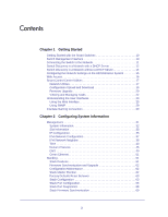 3
3 -
 4
4 -
 5
5 -
 6
6 -
 7
7 -
8
-
9
-
10
-
11
-
12
-
13
-
14
-
15
-
16
-
17
-
18
-
19
-
20
-
21
-
22
-
23
-
24
-
25
-
26
-
27
-
28
-
29
-
30
-
31
-
32
-
33
-
34
-
35
-
36
-
37
-
38
-
39
-
40
-
41
-
42
-
43
-
44
-
45
-
46
-
47
-
48
-
49
-
50
-
51
-
52
-
53
-
54
-
55
-
56
-
57
-
58
-
59
-
60
-
61
-
62
-
63
-
64
-
65
-
66
-
67
-
68
-
69
-
70
-
71
-
72
-
73
-
74
-
75
-
76
-
77
-
78
-
79
-
80
-
81
-
82
-
83
-
84
-
85
-
86
-
87
-
88
-
89
-
90
-
91
-
92
-
93
-
94
-
95
-
96
-
97
-
98
-
99
-
100
-
101
-
102
-
103
-
104
-
105
-
106
-
107
-
108
-
109
-
110
-
111
-
112
-
113
-
114
-
115
-
116
-
117
-
118
-
119
-
120
-
121
-
122
-
123
-
124
-
125
-
126
-
127
-
128
-
129
-
130
-
131
-
132
-
133
-
134
-
135
-
136
-
137
-
138
-
139
-
140
-
141
-
142
-
143
-
144
-
145
-
146
-
147
-
148
-
149
-
150
-
151
-
152
-
153
-
154
-
155
-
156
-
157
-
158
-
159
-
160
-
161
-
162
-
163
-
164
-
165
-
166
-
167
-
168
-
169
-
170
-
171
-
172
-
173
-
174
-
175
-
176
-
177
-
178
-
179
-
180
-
181
-
182
-
183
-
184
-
185
-
186
-
187
-
188
-
189
-
190
-
191
-
192
-
193
-
194
-
195
-
196
-
197
-
198
-
199
-
200
-
201
-
202
-
203
-
204
-
205
-
206
-
207
-
208
-
209
-
210
-
211
-
212
-
213
-
214
-
215
-
216
-
217
-
218
-
219
-
220
-
221
-
222
-
223
-
224
-
225
-
226
-
227
-
228
-
229
-
230
-
231
-
232
-
233
-
234
-
235
-
236
-
237
-
238
-
239
-
240
-
241
-
242
-
243
-
244
-
245
-
246
-
247
-
248
-
249
-
250
-
251
-
252
-
253
-
254
-
255
-
256
-
257
-
258
-
259
-
260
-
261
-
262
-
263
-
264
-
265
-
266
-
267
-
268
-
269
-
270
-
271
-
272
-
273
-
274
-
275
-
276
-
277
-
278
-
279
-
280
-
281
-
282
-
283
-
284
-
285
-
286
-
287
-
288
-
289
-
290
-
291
-
292
-
293
-
294
-
295
-
296
-
297
-
298
-
299
-
300
-
301
-
302
-
303
-
304
-
305
-
306
-
307
-
308
-
309
-
310
-
311
-
312
-
313
-
314
-
315
-
316
-
317
-
318
-
319
-
320
-
321
-
322
-
323
-
324
-
325
-
326
-
327
-
328
-
329
 |
 |

350 East Plumeria Drive
San Jose, CA 95134
USA
February 2012
202-10995-01
v1.0
GS728TS, GS728TPS,
GS752TS, and GS752TPS
Gigabit Smart Switches
Software Administration Manual