Netgear GS752TS GS7xxTS-TPS Software Admin Manual - Page 124
Configuration Name, Configuration Revision Level, Cancel, Apply, Refresh
 |
View all Netgear GS752TS manuals
Add to My Manuals
Save this manual to your list of manuals |
Page 124 highlights
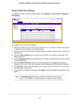
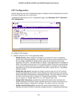
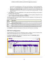
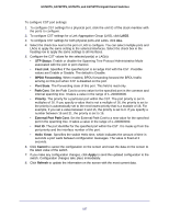
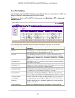
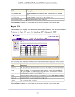
GS728TS, GS728TPS, GS752TS, and GS752TPS Gigabit Smart Switches 3. Specify the configuration name and revision level. • Configuration Name. Name used to identify the configuration currently being used. It may be up to 32 alphanumeric characters. • Configuration Revision Level. Number used to identify the configuration currently being used. The values allowed are between 0 and 65535. The default value is 0. 4. Specify the BPDU Flooding status for all ports or for individual ports. When this feature is enabled, BPDU packets arriving at this port are flooded to other ports if STP is disabled. 5. Click Cancel to cancel the configuration on the screen and reset the data on the screen to the latest value of the switch 6. If you make any configuration changes, click Apply to send the updated configuration to the switch. Configuration changes occur immediately. The following table describes the STP Status information displayed on the screen. Field Description Bridge Identifier The bridge identifier for the CST. It is made up using the bridge priority and the base MAC address of the bridge. Time Since Topology Change The time in seconds since the topology of the CST last changed. Topology Change Count The number of times the topology has changed for the CST. Topology Change The value of the topology change parameter for the switch indicating if a topology change is in progress on any port assigned to the CST. The value is either True or False. Designated Root The bridge identifier of the root bridge. It is made up from the bridge priority and the base MAC address of the bridge. Root Path Cost Path cost to the Designated Root for the CST. Root Port Port to access the Designated Root for the CST. Max Age (secs) Specifies the bridge maximum age for CST. The value must be less than or equal to (2 X Bridge Forward Delay) - 1 and greater than or equal to 2 X (Bridge Hello Time +1). Forward Delay (secs) Derived value of the Root Port Bridge Forward Delay parameter. Hold TIme (secs) Minimum time between transmission of Configuration BPDUs. CST Regional Root Priority and base MAC address of the CST Regional Root. CST Path Cost Path Cost to the CST tree Regional Root. Click Refresh to update the information on the screen with the most current data. 124
-
 1
1 -
2
-
3
-
4
-
5
-
6
-
7
-
8
-
9
-
10
-
11
-
12
-
13
-
14
-
15
-
16
-
17
-
18
-
19
-
20
-
21
-
22
-
23
-
24
-
25
-
26
-
27
-
28
-
29
-
30
-
31
-
32
-
33
-
34
-
35
-
36
-
37
-
38
-
39
-
40
-
41
-
42
-
43
-
44
-
45
-
46
-
47
-
48
-
49
-
50
-
51
-
52
-
53
-
54
-
55
-
56
-
57
-
58
-
59
-
60
-
61
-
62
-
63
-
64
-
65
-
66
-
67
-
68
-
69
-
70
-
71
-
72
-
73
-
74
-
75
-
76
-
77
-
78
-
79
-
80
-
81
-
82
-
83
-
84
-
85
-
86
-
87
-
88
-
89
-
90
-
91
-
92
-
93
-
94
-
95
-
96
-
97
-
98
-
99
-
100
-
101
-
102
-
103
-
104
-
105
-
106
-
107
-
108
-
109
-
110
-
111
-
112
-
113
-
114
-
115
-
116
-
117
-
118
-
 119
119 -
 120
120 -
 121
121 -
 122
122 -
 123
123 -
 124
124 -
 125
125 -
 126
126 -
 127
127 -
 128
128 -
 129
129 -
130
-
131
-
132
-
133
-
134
-
135
-
136
-
137
-
138
-
139
-
140
-
141
-
142
-
143
-
144
-
145
-
146
-
147
-
148
-
149
-
150
-
151
-
152
-
153
-
154
-
155
-
156
-
157
-
158
-
159
-
160
-
161
-
162
-
163
-
164
-
165
-
166
-
167
-
168
-
169
-
170
-
171
-
172
-
173
-
174
-
175
-
176
-
177
-
178
-
179
-
180
-
181
-
182
-
183
-
184
-
185
-
186
-
187
-
188
-
189
-
190
-
191
-
192
-
193
-
194
-
195
-
196
-
197
-
198
-
199
-
200
-
201
-
202
-
203
-
204
-
205
-
206
-
207
-
208
-
209
-
210
-
211
-
212
-
213
-
214
-
215
-
216
-
217
-
218
-
219
-
220
-
221
-
222
-
223
-
224
-
225
-
226
-
227
-
228
-
229
-
230
-
231
-
232
-
233
-
234
-
235
-
236
-
237
-
238
-
239
-
240
-
241
-
242
-
243
-
244
-
245
-
246
-
247
-
248
-
249
-
250
-
251
-
252
-
253
-
254
-
255
-
256
-
257
-
258
-
259
-
260
-
261
-
262
-
263
-
264
-
265
-
266
-
267
-
268
-
269
-
270
-
271
-
272
-
273
-
274
-
275
-
276
-
277
-
278
-
279
-
280
-
281
-
282
-
283
-
284
-
285
-
286
-
287
-
288
-
289
-
290
-
291
-
292
-
293
-
294
-
295
-
296
-
297
-
298
-
299
-
300
-
301
-
302
-
303
-
304
-
305
-
306
-
307
-
308
-
309
-
310
-
311
-
312
-
313
-
314
-
315
-
316
-
317
-
318
-
319
-
320
-
321
-
322
-
323
-
324
-
325
-
326
-
327
-
328
-
329
 |
 |