Netgear GS752TS GS7xxTS-TPS Software Admin Manual - Page 122
Spanning Tree Protocol, Cancel, Apply
 |
View all Netgear GS752TS manuals
Add to My Manuals
Save this manual to your list of manuals |
Page 122 highlights
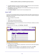
GS728TS, GS728TPS, GS752TS, and GS752TPS Gigabit Smart Switches 4. Select the check box next to the port or LAG to configure. You can select multiple ports and LAGs to apply the same setting to the selected interfaces. Select the check box in the heading row to apply the same settings to all interfaces. 5. From the Auto-VoIP Mode menu, specify whether to enable or disable Auto-VoIP on the selected port(s) or LAG(s). 6. Click Cancel to cancel the configuration on the screen and reset the data on the screen to the latest value of the switch. 7. If you make any changes to this page, click Apply to send the updated configuration to the switch. Spanning Tree Protocol The Spanning Tree Protocol (STP) provides a tree topology for any arrangement of bridges. STP also provides one path between end stations on a network, eliminating loops. Spanning tree versions supported include Common STP, Multiple STP, and Rapid STP. Classic STP provides a single path between end stations, avoiding and eliminating loops. For information on configuring Common STP, see CST Port Configuration on page 126. Multiple Spanning Tree Protocol (MSTP) supports multiple instances of Spanning Tree to efficiently channel VLAN traffic over different interfaces. Each instance of the Spanning Tree behaves in the manner specified in IEEE 802.1w, Rapid Spanning Tree (RSTP), with slight modifications in the working but not the end effect (chief among the effects, is the rapid transitioning of the port to 'Forwarding'). The difference between the RSTP and the traditional STP (IEEE 802.1D) is the ability to configure and recognize full-duplex connectivity and ports which are connected to end stations, resulting in rapid transitioning of the port to 'Forwarding' state and the suppression of Topology Change Notification. These features are represented by the parameters 'pointtopoint' and 'edgeport'. MSTP is compatible to both RSTP and STP. It behaves appropriately to STP and RSTP bridges. A MSTP bridge can be configured to behave entirely as a RSTP bridge or a STP bridge. Note: For two bridges to be in the same region, the force version should be 802.1s and their configuration name, digest key, and revision level should match. For additional information about regions and their effect on network topology, refer to the IEEE 802.1Q standard. From the STP link, you can access the following pages: • STP Switch Configuration on page 123 • CST Configuration on page 125 • CST Port Configuration on page 126 • CST Port Status on page 128 • Rapid STP on page 129 122
-
 1
1 -
2
-
3
-
4
-
5
-
6
-
7
-
8
-
9
-
10
-
11
-
12
-
13
-
14
-
15
-
16
-
17
-
18
-
19
-
20
-
21
-
22
-
23
-
24
-
25
-
26
-
27
-
28
-
29
-
30
-
31
-
32
-
33
-
34
-
35
-
36
-
37
-
38
-
39
-
40
-
41
-
42
-
43
-
44
-
45
-
46
-
47
-
48
-
49
-
50
-
51
-
52
-
53
-
54
-
55
-
56
-
57
-
58
-
59
-
60
-
61
-
62
-
63
-
64
-
65
-
66
-
67
-
68
-
69
-
70
-
71
-
72
-
73
-
74
-
75
-
76
-
77
-
78
-
79
-
80
-
81
-
82
-
83
-
84
-
85
-
86
-
87
-
88
-
89
-
90
-
91
-
92
-
93
-
94
-
95
-
96
-
97
-
98
-
99
-
100
-
101
-
102
-
103
-
104
-
105
-
106
-
107
-
108
-
109
-
110
-
111
-
112
-
113
-
114
-
115
-
116
-
 117
117 -
 118
118 -
 119
119 -
 120
120 -
 121
121 -
 122
122 -
 123
123 -
 124
124 -
 125
125 -
 126
126 -
 127
127 -
128
-
129
-
130
-
131
-
132
-
133
-
134
-
135
-
136
-
137
-
138
-
139
-
140
-
141
-
142
-
143
-
144
-
145
-
146
-
147
-
148
-
149
-
150
-
151
-
152
-
153
-
154
-
155
-
156
-
157
-
158
-
159
-
160
-
161
-
162
-
163
-
164
-
165
-
166
-
167
-
168
-
169
-
170
-
171
-
172
-
173
-
174
-
175
-
176
-
177
-
178
-
179
-
180
-
181
-
182
-
183
-
184
-
185
-
186
-
187
-
188
-
189
-
190
-
191
-
192
-
193
-
194
-
195
-
196
-
197
-
198
-
199
-
200
-
201
-
202
-
203
-
204
-
205
-
206
-
207
-
208
-
209
-
210
-
211
-
212
-
213
-
214
-
215
-
216
-
217
-
218
-
219
-
220
-
221
-
222
-
223
-
224
-
225
-
226
-
227
-
228
-
229
-
230
-
231
-
232
-
233
-
234
-
235
-
236
-
237
-
238
-
239
-
240
-
241
-
242
-
243
-
244
-
245
-
246
-
247
-
248
-
249
-
250
-
251
-
252
-
253
-
254
-
255
-
256
-
257
-
258
-
259
-
260
-
261
-
262
-
263
-
264
-
265
-
266
-
267
-
268
-
269
-
270
-
271
-
272
-
273
-
274
-
275
-
276
-
277
-
278
-
279
-
280
-
281
-
282
-
283
-
284
-
285
-
286
-
287
-
288
-
289
-
290
-
291
-
292
-
293
-
294
-
295
-
296
-
297
-
298
-
299
-
300
-
301
-
302
-
303
-
304
-
305
-
306
-
307
-
308
-
309
-
310
-
311
-
312
-
313
-
314
-
315
-
316
-
317
-
318
-
319
-
320
-
321
-
322
-
323
-
324
-
325
-
326
-
327
-
328
-
329
 |
 |