Netgear GS752TS GS7xxTS-TPS Software Admin Manual - Page 261
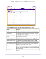
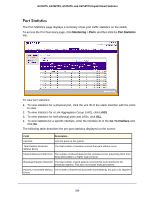
information about a different port, select the port number from the Interface menu.
 |
View all Netgear GS752TS manuals
Add to My Manuals
Save this manual to your list of manuals |
Page 261 highlights
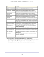
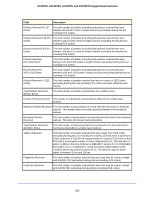
GS728TS, GS728TPS, GS752TS, and GS752TPS Gigabit Smart Switches The following table describes the detailed port information displayed on the screen. To view information about a different port, select the port number from the Interface menu. Field Interface MST ID ifIndex Port Type Port Channel ID Port Role STP Mode STP State Admin Mode Description Use the drop down menu to select the interface for which data is to be displayed or configured. Displays the created or existing MSTs. This field indicates the ifIndex of the interface table entry associated with this port on an adapter. For most ports this field is blank. Otherwise the possible values are: • Mirrored: Indicates that the port has been configured as a monitoring port and is the source port in a port mirroring session. For additional information about port monitoring and probe ports, see Multiple Port Mirroring on page 278. • Probe: Indicates that the port has been configured as a monitoring port and is the destination port in a port mirroring session. For additional information about port monitoring and probe ports, see Multiple Port Mirroring on page 278. • Port Channel: Indicates that the port has been configured as a member of a port-channel, which is also known as a link Aggregation Group (LAG). If the port is a member of a port channel, the port channel's interface ID and name are shown. Otherwise, Disable is shown. Each MST Bridge Port that is enabled is assigned a Port Role for each spanning tree. The port role will be one of the following values: Root Port, Designated Port, Alternate Port, Backup Port, Master Port, or Disabled Port. Displays the Spanning Tree Protocol (STP) Administrative Mode for the port or LAG. The possible values for this field are: • Enable: Enables the Spanning Tree Protocol for this port. • Disable: Disables the Spanning Tree Protocol for this port. Displays the port's current state Spanning Tree state. This state controls what action a port takes on receipt of a frame. If the bridge detects a malfunctioning port it will place that port into the broken state. The other five states are defined in IEEE 802.1D: • Disabled • Blocking • Listening • Learning • Forwarding • Broken Displays the port control administration state: • Enable: The port can participate in the network (default). • Disable: The port is administratively down and does not participate in the network. 261
-
 1
1 -
2
-
3
-
4
-
5
-
6
-
7
-
8
-
9
-
10
-
11
-
12
-
13
-
14
-
15
-
16
-
17
-
18
-
19
-
20
-
21
-
22
-
23
-
24
-
25
-
26
-
27
-
28
-
29
-
30
-
31
-
32
-
33
-
34
-
35
-
36
-
37
-
38
-
39
-
40
-
41
-
42
-
43
-
44
-
45
-
46
-
47
-
48
-
49
-
50
-
51
-
52
-
53
-
54
-
55
-
56
-
57
-
58
-
59
-
60
-
61
-
62
-
63
-
64
-
65
-
66
-
67
-
68
-
69
-
70
-
71
-
72
-
73
-
74
-
75
-
76
-
77
-
78
-
79
-
80
-
81
-
82
-
83
-
84
-
85
-
86
-
87
-
88
-
89
-
90
-
91
-
92
-
93
-
94
-
95
-
96
-
97
-
98
-
99
-
100
-
101
-
102
-
103
-
104
-
105
-
106
-
107
-
108
-
109
-
110
-
111
-
112
-
113
-
114
-
115
-
116
-
117
-
118
-
119
-
120
-
121
-
122
-
123
-
124
-
125
-
126
-
127
-
128
-
129
-
130
-
131
-
132
-
133
-
134
-
135
-
136
-
137
-
138
-
139
-
140
-
141
-
142
-
143
-
144
-
145
-
146
-
147
-
148
-
149
-
150
-
151
-
152
-
153
-
154
-
155
-
156
-
157
-
158
-
159
-
160
-
161
-
162
-
163
-
164
-
165
-
166
-
167
-
168
-
169
-
170
-
171
-
172
-
173
-
174
-
175
-
176
-
177
-
178
-
179
-
180
-
181
-
182
-
183
-
184
-
185
-
186
-
187
-
188
-
189
-
190
-
191
-
192
-
193
-
194
-
195
-
196
-
197
-
198
-
199
-
200
-
201
-
202
-
203
-
204
-
205
-
206
-
207
-
208
-
209
-
210
-
211
-
212
-
213
-
214
-
215
-
216
-
217
-
218
-
219
-
220
-
221
-
222
-
223
-
224
-
225
-
226
-
227
-
228
-
229
-
230
-
231
-
232
-
233
-
234
-
235
-
236
-
237
-
238
-
239
-
240
-
241
-
242
-
243
-
244
-
245
-
246
-
247
-
248
-
249
-
250
-
251
-
252
-
253
-
254
-
255
-
 256
256 -
 257
257 -
 258
258 -
 259
259 -
 260
260 -
 261
261 -
 262
262 -
 263
263 -
 264
264 -
 265
265 -
 266
266 -
267
-
268
-
269
-
270
-
271
-
272
-
273
-
274
-
275
-
276
-
277
-
278
-
279
-
280
-
281
-
282
-
283
-
284
-
285
-
286
-
287
-
288
-
289
-
290
-
291
-
292
-
293
-
294
-
295
-
296
-
297
-
298
-
299
-
300
-
301
-
302
-
303
-
304
-
305
-
306
-
307
-
308
-
309
-
310
-
311
-
312
-
313
-
314
-
315
-
316
-
317
-
318
-
319
-
320
-
321
-
322
-
323
-
324
-
325
-
326
-
327
-
328
-
329
 |
 |