Netgear GS752TS GS7xxTS-TPS Software Admin Manual - Page 26
Device View, Power/Status LED, FAN Status LED, Stack Master LED, Seven-Segment LED for the Stacking ID
 |
View all Netgear GS752TS manuals
Add to My Manuals
Save this manual to your list of manuals |
Page 26 highlights
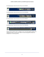
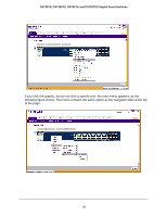
GS728TS, GS728TPS, GS752TS, and GS752TPS Gigabit Smart Switches Device View The Device View is a Java® applet that displays the ports on the switch. This graphic provides an alternate way to navigate to configuration and monitoring options. The graphic also provides information about device ports, current configuration and status, table information, and feature components. The Device View is available from the System> Device View page. Depending upon the status of the port, the LED of the port status illuminates in Device View either red, green, or gray. Green indicates that the port is enabled. Red indicates that an error has occurred on the port, or red indicates that the link is disabled. Gray is applicable for ports 27 and 28 on the GS728TS/GS728TPS and ports 51 and 52 on the GS752TS/GS752TPS and indicates that the port is working in stack mode. The LED of the port speed illuminates either green or yellow. • A green LED indicates operational ports at 1 Gbps or 2.5 Gbps (if used for stacking) link speed. • A yellow LED indicates operational ports at 10/100 Mbps link speed. The System LEDs are located on the left side of the front panel. Power/Status LED The power LED is a bicolor LED that serves as an indicator of power and diagnostic status. The following indications are given by the following LED states: • A solid Green LED indicates that the power is supplied to the switch and operating normally. • A solid Yellow LED indicates that system is in the boot-up stage. • No lit LED indicates that power is disconnected. FAN Status LED FAN status is indicated as follows: • A solid yellow LED indicates that the fan is faulty. • No lit LED indicates that the fan is operating normally. Stack Master LED The Stack Master LED is lit if there is an active stack link and the unit is in stack mode. • A solid Green LED indicates that the switch acts as a master unit in a stack of switches. • No lit LED indicates that the switch acts as a slave member in a stack of switches. Seven-Segment LED for the Stacking ID A solid Green LED displays the stack ID (1-6). 26
-
 1
1 -
2
-
3
-
4
-
5
-
6
-
7
-
8
-
9
-
10
-
11
-
12
-
13
-
14
-
15
-
16
-
17
-
18
-
19
-
20
-
 21
21 -
 22
22 -
 23
23 -
 24
24 -
 25
25 -
 26
26 -
 27
27 -
 28
28 -
 29
29 -
 30
30 -
 31
31 -
32
-
33
-
34
-
35
-
36
-
37
-
38
-
39
-
40
-
41
-
42
-
43
-
44
-
45
-
46
-
47
-
48
-
49
-
50
-
51
-
52
-
53
-
54
-
55
-
56
-
57
-
58
-
59
-
60
-
61
-
62
-
63
-
64
-
65
-
66
-
67
-
68
-
69
-
70
-
71
-
72
-
73
-
74
-
75
-
76
-
77
-
78
-
79
-
80
-
81
-
82
-
83
-
84
-
85
-
86
-
87
-
88
-
89
-
90
-
91
-
92
-
93
-
94
-
95
-
96
-
97
-
98
-
99
-
100
-
101
-
102
-
103
-
104
-
105
-
106
-
107
-
108
-
109
-
110
-
111
-
112
-
113
-
114
-
115
-
116
-
117
-
118
-
119
-
120
-
121
-
122
-
123
-
124
-
125
-
126
-
127
-
128
-
129
-
130
-
131
-
132
-
133
-
134
-
135
-
136
-
137
-
138
-
139
-
140
-
141
-
142
-
143
-
144
-
145
-
146
-
147
-
148
-
149
-
150
-
151
-
152
-
153
-
154
-
155
-
156
-
157
-
158
-
159
-
160
-
161
-
162
-
163
-
164
-
165
-
166
-
167
-
168
-
169
-
170
-
171
-
172
-
173
-
174
-
175
-
176
-
177
-
178
-
179
-
180
-
181
-
182
-
183
-
184
-
185
-
186
-
187
-
188
-
189
-
190
-
191
-
192
-
193
-
194
-
195
-
196
-
197
-
198
-
199
-
200
-
201
-
202
-
203
-
204
-
205
-
206
-
207
-
208
-
209
-
210
-
211
-
212
-
213
-
214
-
215
-
216
-
217
-
218
-
219
-
220
-
221
-
222
-
223
-
224
-
225
-
226
-
227
-
228
-
229
-
230
-
231
-
232
-
233
-
234
-
235
-
236
-
237
-
238
-
239
-
240
-
241
-
242
-
243
-
244
-
245
-
246
-
247
-
248
-
249
-
250
-
251
-
252
-
253
-
254
-
255
-
256
-
257
-
258
-
259
-
260
-
261
-
262
-
263
-
264
-
265
-
266
-
267
-
268
-
269
-
270
-
271
-
272
-
273
-
274
-
275
-
276
-
277
-
278
-
279
-
280
-
281
-
282
-
283
-
284
-
285
-
286
-
287
-
288
-
289
-
290
-
291
-
292
-
293
-
294
-
295
-
296
-
297
-
298
-
299
-
300
-
301
-
302
-
303
-
304
-
305
-
306
-
307
-
308
-
309
-
310
-
311
-
312
-
313
-
314
-
315
-
316
-
317
-
318
-
319
-
320
-
321
-
322
-
323
-
324
-
325
-
326
-
327
-
328
-
329
 |
 |