Netgear GS752TS GS7xxTS-TPS Software Admin Manual - Page 236
ACL Based on Destination IPv6 L4 Port
 |
View all Netgear GS752TS manuals
Add to My Manuals
Save this manual to your list of manuals |
Page 236 highlights
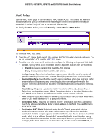
GS728TS, GS728TPS, GS752TS, and GS752TPS Gigabit Smart Switches • ACL Based on Source IPv4 - Use this to create a ACL based on the source IPv4 address and IPv4 address mask. • ACL Based on Destination IPv6 - Use this to create a ACL based on the destination IPv6 prefix and IPv6 prefix length. • ACL Based on Source IPv6 - Use this to create a ACL based on the source IPv6 prefix and IPv6 prefix length. • ACL Based on Destination IPv4 L4 Port - Use this to create a ACL based on the destination IPv4 layer4 port number. • ACL Based on Source IPv4 L4 Port - Use this to create a ACL based on the source IPv4 layer4 port number. • ACL Based on Destination IPv6 L4 Port - Use this to create a ACL based on the destination IPv6 layer4 port number. • ACL Based on Source IPv6 L4 Port - Use this to create a ACL based on the source IPv6 layer4 port number. 2. In the Rule ID field, enter a whole number in the range of (1 to 10) that will be used to identify the rule. 3. In the Action field, specify what action should be taken if a packet matches the rule's criteria. The choices are permit or deny. 4. In the Match Every field, specify True or False. If you select True, all packets are considered to match the rule criteria, and no other fields are configurable. 5. Specify the match criteria for the rule. The fields available for match criteria input depend on the selected ACL type. 6. To add a new rule to the ACL, select the check box next to the Rule ID, then click Add. You can add multiple rules to the same ACL type. 7. In the Binding Configuration area, specify the packet filtering direction for an ACL in the Direction field. The only valid direction is Inbound. 8. In the Port Selection Table area, select the interfaces for ACL mapping. All non-routing physical ports and LAGs are listed. 9. To cancel the configuration on the screen. Reset the data on the screen to the latest value of the switch, then click Cancel. 10. To send the updated configuration to the switch, click Apply. Configuration changes take effect immediately. 236
-
 1
1 -
2
-
3
-
4
-
5
-
6
-
7
-
8
-
9
-
10
-
11
-
12
-
13
-
14
-
15
-
16
-
17
-
18
-
19
-
20
-
21
-
22
-
23
-
24
-
25
-
26
-
27
-
28
-
29
-
30
-
31
-
32
-
33
-
34
-
35
-
36
-
37
-
38
-
39
-
40
-
41
-
42
-
43
-
44
-
45
-
46
-
47
-
48
-
49
-
50
-
51
-
52
-
53
-
54
-
55
-
56
-
57
-
58
-
59
-
60
-
61
-
62
-
63
-
64
-
65
-
66
-
67
-
68
-
69
-
70
-
71
-
72
-
73
-
74
-
75
-
76
-
77
-
78
-
79
-
80
-
81
-
82
-
83
-
84
-
85
-
86
-
87
-
88
-
89
-
90
-
91
-
92
-
93
-
94
-
95
-
96
-
97
-
98
-
99
-
100
-
101
-
102
-
103
-
104
-
105
-
106
-
107
-
108
-
109
-
110
-
111
-
112
-
113
-
114
-
115
-
116
-
117
-
118
-
119
-
120
-
121
-
122
-
123
-
124
-
125
-
126
-
127
-
128
-
129
-
130
-
131
-
132
-
133
-
134
-
135
-
136
-
137
-
138
-
139
-
140
-
141
-
142
-
143
-
144
-
145
-
146
-
147
-
148
-
149
-
150
-
151
-
152
-
153
-
154
-
155
-
156
-
157
-
158
-
159
-
160
-
161
-
162
-
163
-
164
-
165
-
166
-
167
-
168
-
169
-
170
-
171
-
172
-
173
-
174
-
175
-
176
-
177
-
178
-
179
-
180
-
181
-
182
-
183
-
184
-
185
-
186
-
187
-
188
-
189
-
190
-
191
-
192
-
193
-
194
-
195
-
196
-
197
-
198
-
199
-
200
-
201
-
202
-
203
-
204
-
205
-
206
-
207
-
208
-
209
-
210
-
211
-
212
-
213
-
214
-
215
-
216
-
217
-
218
-
219
-
220
-
221
-
222
-
223
-
224
-
225
-
226
-
227
-
228
-
229
-
230
-
 231
231 -
 232
232 -
 233
233 -
 234
234 -
 235
235 -
 236
236 -
 237
237 -
 238
238 -
 239
239 -
 240
240 -
 241
241 -
242
-
243
-
244
-
245
-
246
-
247
-
248
-
249
-
250
-
251
-
252
-
253
-
254
-
255
-
256
-
257
-
258
-
259
-
260
-
261
-
262
-
263
-
264
-
265
-
266
-
267
-
268
-
269
-
270
-
271
-
272
-
273
-
274
-
275
-
276
-
277
-
278
-
279
-
280
-
281
-
282
-
283
-
284
-
285
-
286
-
287
-
288
-
289
-
290
-
291
-
292
-
293
-
294
-
295
-
296
-
297
-
298
-
299
-
300
-
301
-
302
-
303
-
304
-
305
-
306
-
307
-
308
-
309
-
310
-
311
-
312
-
313
-
314
-
315
-
316
-
317
-
318
-
319
-
320
-
321
-
322
-
323
-
324
-
325
-
326
-
327
-
328
-
329
 |
 |