Netgear GS752TS GS7xxTS-TPS Software Admin Manual - Page 180
Interface Queue Configuration, Interface Trust Mode, Untrusted, Interface Shaping Rate, Cancel, Apply
 |
View all Netgear GS752TS manuals
Add to My Manuals
Save this manual to your list of manuals |
Page 180 highlights
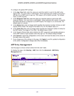
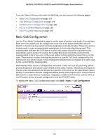
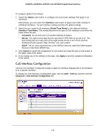
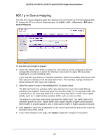
GS728TS, GS728TPS, GS752TS, and GS752TPS Gigabit Smart Switches To configure CoS settings for an interface: 1. To configure CoS settings for a physical port, click the unit ID of the stack member with the ports to configure. 2. To configure CoS settings for a Link Aggregation Group (LAG), click LAGS. 3. To configure CoS settings for both physical ports and LAGs, click ALL. 4. Select the check box next to the port or LAG to configure. You can select multiple ports and LAGs to apply the same setting to the selected interfaces. 5. From the Interface Trust Mode field, specify whether or not the selected interface(s) trust a particular packet marking when the packet enters the port. • Untrusted. Do not trust any CoS packet marking at ingress. • 802.1p. The eight priority tags that are specified in IEEE 802.1p are p0 to p7. The QoS setting lets you map each of the eight priority levels to one of four internal hardware priority queues: High, Normal, Low, and Lowest. • DSCP. The six most significant bits of the DiffServ field are called the Differentiated Services Code Point (DSCP) bits. 6. From the Interface Shaping Rate field, specify the maximum bandwidth allowed on the selected interface(s). This setting is typically used to shape the outbound transmission rate in increments of 64 kbps. This value is controlled independently of any per-queue maximum bandwidth configuration. It is effectively a second-level shaping mechanism. The default value is 0, in increments of 16. A value of 0 means the maximum is unlimited. The expected shaping at egress interface is calculated as: (frameSize × shaping × 64) ÷ (frameSize+IFG), where IFG (Inter frame gap) is 20 bytes, frameSize is the configured frame size of the traffic, and shaping is the configured traffic shaping in the Interface Shaping Rate field. For example, when a 64 byte frame size and 64 kbps interface shaping rate are configured, the expected shaping will be approximately 3121 kbps. 7. Click Cancel to cancel the configuration on the screen and reset the data on the screen to the latest value of the switch. 8. If you make changes to the page, click Apply to apply the changes to the system. Interface Queue Configuration Use the Interface Queue Configuration page to define what a particular queue does by configuring switch egress queues. User-configurable parameters control the amount of bandwidth used by the queue, the queue depth during times of congestion, and the scheduling of packet transmission from the set of all queues on a port. Each port has its own CoS queue-related configuration. The configuration process is simplified by allowing each CoS queue parameter to be configured globally or per-port. A global configuration change is automatically applied to all ports in the system. 180
-
 1
1 -
2
-
3
-
4
-
5
-
6
-
7
-
8
-
9
-
10
-
11
-
12
-
13
-
14
-
15
-
16
-
17
-
18
-
19
-
20
-
21
-
22
-
23
-
24
-
25
-
26
-
27
-
28
-
29
-
30
-
31
-
32
-
33
-
34
-
35
-
36
-
37
-
38
-
39
-
40
-
41
-
42
-
43
-
44
-
45
-
46
-
47
-
48
-
49
-
50
-
51
-
52
-
53
-
54
-
55
-
56
-
57
-
58
-
59
-
60
-
61
-
62
-
63
-
64
-
65
-
66
-
67
-
68
-
69
-
70
-
71
-
72
-
73
-
74
-
75
-
76
-
77
-
78
-
79
-
80
-
81
-
82
-
83
-
84
-
85
-
86
-
87
-
88
-
89
-
90
-
91
-
92
-
93
-
94
-
95
-
96
-
97
-
98
-
99
-
100
-
101
-
102
-
103
-
104
-
105
-
106
-
107
-
108
-
109
-
110
-
111
-
112
-
113
-
114
-
115
-
116
-
117
-
118
-
119
-
120
-
121
-
122
-
123
-
124
-
125
-
126
-
127
-
128
-
129
-
130
-
131
-
132
-
133
-
134
-
135
-
136
-
137
-
138
-
139
-
140
-
141
-
142
-
143
-
144
-
145
-
146
-
147
-
148
-
149
-
150
-
151
-
152
-
153
-
154
-
155
-
156
-
157
-
158
-
159
-
160
-
161
-
162
-
163
-
164
-
165
-
166
-
167
-
168
-
169
-
170
-
171
-
172
-
173
-
174
-
 175
175 -
 176
176 -
 177
177 -
 178
178 -
 179
179 -
 180
180 -
 181
181 -
 182
182 -
 183
183 -
 184
184 -
 185
185 -
186
-
187
-
188
-
189
-
190
-
191
-
192
-
193
-
194
-
195
-
196
-
197
-
198
-
199
-
200
-
201
-
202
-
203
-
204
-
205
-
206
-
207
-
208
-
209
-
210
-
211
-
212
-
213
-
214
-
215
-
216
-
217
-
218
-
219
-
220
-
221
-
222
-
223
-
224
-
225
-
226
-
227
-
228
-
229
-
230
-
231
-
232
-
233
-
234
-
235
-
236
-
237
-
238
-
239
-
240
-
241
-
242
-
243
-
244
-
245
-
246
-
247
-
248
-
249
-
250
-
251
-
252
-
253
-
254
-
255
-
256
-
257
-
258
-
259
-
260
-
261
-
262
-
263
-
264
-
265
-
266
-
267
-
268
-
269
-
270
-
271
-
272
-
273
-
274
-
275
-
276
-
277
-
278
-
279
-
280
-
281
-
282
-
283
-
284
-
285
-
286
-
287
-
288
-
289
-
290
-
291
-
292
-
293
-
294
-
295
-
296
-
297
-
298
-
299
-
300
-
301
-
302
-
303
-
304
-
305
-
306
-
307
-
308
-
309
-
310
-
311
-
312
-
313
-
314
-
315
-
316
-
317
-
318
-
319
-
320
-
321
-
322
-
323
-
324
-
325
-
326
-
327
-
328
-
329
 |
 |