Netgear GS752TS GS7xxTS-TPS Software Admin Manual - Page 322
Configuring VLAN Routing, Creating VLAN Routing Interfaces
 |
View all Netgear GS752TS manuals
Add to My Manuals
Save this manual to your list of manuals |
Page 322 highlights
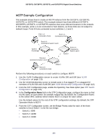
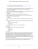
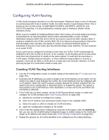
GS728TS, GS728TPS, GS752TS, and GS752TPS Gigabit Smart Switches Configuring VLAN Routing VLANs divide broadcast domains in a LAN environment. Whenever hosts in one VLAN need to communicate with hosts in another VLAN, the traffic must be routed between them. This is known as inter-VLAN routing. On NETGEAR GS728TS, GS728TPS, GS752TS, and GS752TPS switches, it is accomplished by creating Layer 3 interfaces (Switch virtual interfaces (SVI)). When a port is enabled for bridging (default) rather than routing, all normal bridge processing is performed for an inbound packet, which is then associated with a VLAN. Its MAC Destination Address (MAC DA) and VLAN ID are used to search the MAC address table. If routing is enabled for the VLAN, and the MAC DA of an inbound unicast packet is that of the internal bridge-router interface, the packet is routed. An inbound multicast packet is forwarded to all ports in the VLAN, plus the internal bridge-router interface, if it was received on a routed VLAN. Since a port can be configured to belong to more than one VLAN, VLAN routing might be enabled for all of the VLANs on the port, or for a subset. VLAN Routing can be used to allow more than one physical port to reside on the same subnet. It could also be used when a VLAN spans multiple physical networks, or when additional segmentation or security is required. A port can be either a VLAN port or a router port, but not both. However, a VLAN port may be part of a VLAN that is itself a router port. Creating VLAN Routing Interfaces 1. Use the IP Configuration screen to enable routing on the switch (see IP Configuration on page 161). 2. Determine the IP addresses you want to assign to the VLAN interface on the switch. For the switch to be able to route between the VLANs, the VLAN interfaces must be configured with an IP address. When the switch receives a packet destined for another subnet/VLAN, the switch looks at the routing table to determine where to forward the packet. The packet is then passed to the VLAN interface of the destination. It is then sent to the port where the end device is attached. 3. If the VLAN has not been created, use the VLAN Routing Wizard screen to create and configure the VLAN interfaces (see VLAN Routing Wizard on page 165) a. Specify the VLAN ID to configure for routing. b. Enter the IP address and associated subnet mask in the available fields. c. Select the ports or LAGs to include as VLAN members. d. Apply the configuration changes to the switch. 4. If the VLAN has already been configured by using the VLAN pages under the Switching tab, you can use the VLAN Routing Configuration page to enable routing on the VLAN and assign an IP address and subnet mask (see VLAN Routing Configuration on page 167). 5. Repeat this process for all VLANs identified to be configured as the routing interfaces. 322
-
 1
1 -
2
-
3
-
4
-
5
-
6
-
7
-
8
-
9
-
10
-
11
-
12
-
13
-
14
-
15
-
16
-
17
-
18
-
19
-
20
-
21
-
22
-
23
-
24
-
25
-
26
-
27
-
28
-
29
-
30
-
31
-
32
-
33
-
34
-
35
-
36
-
37
-
38
-
39
-
40
-
41
-
42
-
43
-
44
-
45
-
46
-
47
-
48
-
49
-
50
-
51
-
52
-
53
-
54
-
55
-
56
-
57
-
58
-
59
-
60
-
61
-
62
-
63
-
64
-
65
-
66
-
67
-
68
-
69
-
70
-
71
-
72
-
73
-
74
-
75
-
76
-
77
-
78
-
79
-
80
-
81
-
82
-
83
-
84
-
85
-
86
-
87
-
88
-
89
-
90
-
91
-
92
-
93
-
94
-
95
-
96
-
97
-
98
-
99
-
100
-
101
-
102
-
103
-
104
-
105
-
106
-
107
-
108
-
109
-
110
-
111
-
112
-
113
-
114
-
115
-
116
-
117
-
118
-
119
-
120
-
121
-
122
-
123
-
124
-
125
-
126
-
127
-
128
-
129
-
130
-
131
-
132
-
133
-
134
-
135
-
136
-
137
-
138
-
139
-
140
-
141
-
142
-
143
-
144
-
145
-
146
-
147
-
148
-
149
-
150
-
151
-
152
-
153
-
154
-
155
-
156
-
157
-
158
-
159
-
160
-
161
-
162
-
163
-
164
-
165
-
166
-
167
-
168
-
169
-
170
-
171
-
172
-
173
-
174
-
175
-
176
-
177
-
178
-
179
-
180
-
181
-
182
-
183
-
184
-
185
-
186
-
187
-
188
-
189
-
190
-
191
-
192
-
193
-
194
-
195
-
196
-
197
-
198
-
199
-
200
-
201
-
202
-
203
-
204
-
205
-
206
-
207
-
208
-
209
-
210
-
211
-
212
-
213
-
214
-
215
-
216
-
217
-
218
-
219
-
220
-
221
-
222
-
223
-
224
-
225
-
226
-
227
-
228
-
229
-
230
-
231
-
232
-
233
-
234
-
235
-
236
-
237
-
238
-
239
-
240
-
241
-
242
-
243
-
244
-
245
-
246
-
247
-
248
-
249
-
250
-
251
-
252
-
253
-
254
-
255
-
256
-
257
-
258
-
259
-
260
-
261
-
262
-
263
-
264
-
265
-
266
-
267
-
268
-
269
-
270
-
271
-
272
-
273
-
274
-
275
-
276
-
277
-
278
-
279
-
280
-
281
-
282
-
283
-
284
-
285
-
286
-
287
-
288
-
289
-
290
-
291
-
292
-
293
-
294
-
295
-
296
-
297
-
298
-
299
-
300
-
301
-
302
-
303
-
304
-
305
-
306
-
307
-
308
-
309
-
310
-
311
-
312
-
313
-
314
-
315
-
316
-
 317
317 -
 318
318 -
 319
319 -
 320
320 -
 321
321 -
 322
322 -
 323
323 -
 324
324 -
 325
325 -
 326
326 -
 327
327 -
328
-
329
 |
 |