Netgear GS752TS GS7xxTS-TPS Software Admin Manual - Page 318
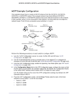
MSTP, Tree Instance MSTI, within Multiple Spanning Tree MST Regions composed of LANs
 |
View all Netgear GS752TS manuals
Add to My Manuals
Save this manual to your list of manuals |
Page 318 highlights
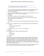
GS728TS, GS728TPS, GS752TS, and GS752TPS Gigabit Smart Switches For more information, see RADIUS Configuration on page 199. 7. Click Add. 8. From the Authentication List screen, configure the default List to use RADIUS as the first authentication method (See Authentication List Configuration on page 207). This example enables 802.1X-based port security on the GS728TS, GS728TPS, GS752TS, or GS752TPS switch and prompts the hosts connected on ports 5-8 for an 802.1X-based authentication. The switch passes the authentication information to the configured RADIUS server. MSTP Spanning Tree Protocol (STP) runs on bridged networks to help eliminate loops. If a bridge loop occurs, the network can become flooded with traffic. IEEE 802.1s Multiple Spanning Tree Protocol (MSTP) supports multiple instances of Spanning Tree to efficiently channel VLAN traffic over different interfaces. Each instance of the Spanning Tree behaves in the manner specified in IEEE 802.1w, Rapid Spanning Tree, with slight modifications in the working but not the end effect (chief among the effects is the rapid transitioning of the port to the Forwarding state). The difference between the RSTP and the traditional STP (IEEE 802.1D) is the ability to configure and recognize full duplex connectivity and ports that are connected to end stations, resulting in rapid transitioning of the port to the Forwarding state and the suppression of Topology Change Notification. These features are represented by the parameters pointtopoint and edgeport. MSTP is compatible to both RSTP and STP. It behaves appropriately to STP and RSTP bridges. A MSTP bridge can be configured to behave entirely as a RSTP bridge or a STP bridge. So, an IEEE 802.1s bridge inherently also supports IEEE 802.1w and IEEE 802.1D. The MSTP algorithm and protocol provides simple and full connectivity for frames assigned to any given VLAN throughout a Bridged LAN comprising arbitrarily interconnected networking devices, each operating MSTP, STP or RSTP. MSTP allows frames assigned to different VLANs to follow separate paths, each based on an independent Multiple Spanning Tree Instance (MSTI), within Multiple Spanning Tree (MST) Regions composed of LANs and or MSTP Bridges. These Regions and the other Bridges and LANs are connected into a single Common Spanning Tree (CST). [IEEE DRAFT P802.1s/D13] MSTP connects all Bridges and LANs with a single Common and Internal Spanning Tree (CIST). The CIST supports the automatic determination of each MST region, choosing its maximum possible extent. The connectivity calculated for the CIST provides the CST for interconnecting these Regions, and an Internal Spanning Tree (IST) within each Region. MSTP ensures that frames with a given VLAN ID are assigned to one and only one of the MSTIs or the IST within the Region, that the assignment is consistent among all the networking devices in the Region and that the stable connectivity of each MSTI and IST at the boundary of the Region matches that of the CST. The stable active topology of the Bridged LAN with respect to frames consistently classified as belonging to any given VLAN thus simply and fully connects all LANs and networking devices throughout the network, 318
-
 1
1 -
2
-
3
-
4
-
5
-
6
-
7
-
8
-
9
-
10
-
11
-
12
-
13
-
14
-
15
-
16
-
17
-
18
-
19
-
20
-
21
-
22
-
23
-
24
-
25
-
26
-
27
-
28
-
29
-
30
-
31
-
32
-
33
-
34
-
35
-
36
-
37
-
38
-
39
-
40
-
41
-
42
-
43
-
44
-
45
-
46
-
47
-
48
-
49
-
50
-
51
-
52
-
53
-
54
-
55
-
56
-
57
-
58
-
59
-
60
-
61
-
62
-
63
-
64
-
65
-
66
-
67
-
68
-
69
-
70
-
71
-
72
-
73
-
74
-
75
-
76
-
77
-
78
-
79
-
80
-
81
-
82
-
83
-
84
-
85
-
86
-
87
-
88
-
89
-
90
-
91
-
92
-
93
-
94
-
95
-
96
-
97
-
98
-
99
-
100
-
101
-
102
-
103
-
104
-
105
-
106
-
107
-
108
-
109
-
110
-
111
-
112
-
113
-
114
-
115
-
116
-
117
-
118
-
119
-
120
-
121
-
122
-
123
-
124
-
125
-
126
-
127
-
128
-
129
-
130
-
131
-
132
-
133
-
134
-
135
-
136
-
137
-
138
-
139
-
140
-
141
-
142
-
143
-
144
-
145
-
146
-
147
-
148
-
149
-
150
-
151
-
152
-
153
-
154
-
155
-
156
-
157
-
158
-
159
-
160
-
161
-
162
-
163
-
164
-
165
-
166
-
167
-
168
-
169
-
170
-
171
-
172
-
173
-
174
-
175
-
176
-
177
-
178
-
179
-
180
-
181
-
182
-
183
-
184
-
185
-
186
-
187
-
188
-
189
-
190
-
191
-
192
-
193
-
194
-
195
-
196
-
197
-
198
-
199
-
200
-
201
-
202
-
203
-
204
-
205
-
206
-
207
-
208
-
209
-
210
-
211
-
212
-
213
-
214
-
215
-
216
-
217
-
218
-
219
-
220
-
221
-
222
-
223
-
224
-
225
-
226
-
227
-
228
-
229
-
230
-
231
-
232
-
233
-
234
-
235
-
236
-
237
-
238
-
239
-
240
-
241
-
242
-
243
-
244
-
245
-
246
-
247
-
248
-
249
-
250
-
251
-
252
-
253
-
254
-
255
-
256
-
257
-
258
-
259
-
260
-
261
-
262
-
263
-
264
-
265
-
266
-
267
-
268
-
269
-
270
-
271
-
272
-
273
-
274
-
275
-
276
-
277
-
278
-
279
-
280
-
281
-
282
-
283
-
284
-
285
-
286
-
287
-
288
-
289
-
290
-
291
-
292
-
293
-
294
-
295
-
296
-
297
-
298
-
299
-
300
-
301
-
302
-
303
-
304
-
305
-
306
-
307
-
308
-
309
-
310
-
311
-
312
-
 313
313 -
 314
314 -
 315
315 -
 316
316 -
 317
317 -
 318
318 -
 319
319 -
 320
320 -
 321
321 -
 322
322 -
 323
323 -
324
-
325
-
326
-
327
-
328
-
329
 |
 |