Netgear GS752TS GS7xxTS-TPS Software Admin Manual - Page 319
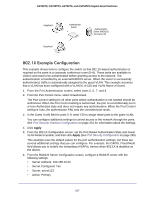
Configuration Table a VLAN ID to MSTID mapping, IEEE DRAFT P802.1s/D13.
 |
View all Netgear GS752TS manuals
Add to My Manuals
Save this manual to your list of manuals |
Page 319 highlights
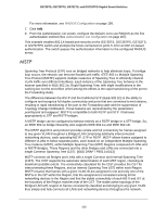
GS728TS, GS728TPS, GS752TS, and GS752TPS Gigabit Smart Switches though frames belonging to different VLANs can take different paths within any Region, per IEEE DRAFT P802.1s/D13. All bridges, whether they use STP, RSTP or MSTP, send information in configuration messages via Bridge Protocol Data Units (BPDUs) to assign port roles that determine each port's participation in a fully and simply connected active topology based on one or more spanning trees. The information communicated is known as the spanning tree priority vector. The BPDU structure for each of these different protocols is different. A MSTP bridge will transmit the appropriate BPDU depending on the received type of BPDU from a particular port. An MST Region comprises of one or more MSTP Bridges with the same MST Configuration Identifier, using the same MSTIs, and which have no Bridges attached that cannot receive and transmit MSTP BPDUs. The MST Configuration Identifier has the following components: 1. Configuration Identifier Format Selector 2. Configuration Name 3. Configuration Revision Level 4. Configuration Digest: 16-byte signature of type HMAC-MD5 created from the MST Configuration Table (a VLAN ID to MSTID mapping) As there are Multiple Instances of Spanning Tree, there is a MSTP state maintained on a per-port, per-instance basis (or on a per port per VLAN basis: as any VLAN can be in one and only one MSTI or CIST). For example, port A can be forwarding for instance 1 while discarding for instance 2. The port states have changed since IEEE 802.1D specification. To support multiple spanning trees, a MSTP bridge has to be configured with an unambiguous assignment of VLAN IDs (VIDs) to spanning trees. This is achieved by: 1. Ensuring that the allocation of VIDs to FIDs is unambiguous. 2. Ensuring that each FID supported by the Bridge is allocated to exactly one Spanning Tree Instance. The combination of VID to FID and then FID to MSTI allocation defines a mapping of VIDs to spanning tree instances, represented by the MST Configuration Table. With this allocation we ensure that every VLAN is assigned to one and only one MSTI. The CIST is also an instance of spanning tree with a MSTID of 0. An instance may occur that has no VIDs allocated to it, but every VLAN must be allocated to one of the other instances of spanning tree. The portion of the active topology of the network that connects any two bridges in the same MST Region traverses only MST bridges and LANs in that region, and never Bridges of any kind outside the Region, in other words connectivity within the region is independent of external connectivity. 319
-
 1
1 -
2
-
3
-
4
-
5
-
6
-
7
-
8
-
9
-
10
-
11
-
12
-
13
-
14
-
15
-
16
-
17
-
18
-
19
-
20
-
21
-
22
-
23
-
24
-
25
-
26
-
27
-
28
-
29
-
30
-
31
-
32
-
33
-
34
-
35
-
36
-
37
-
38
-
39
-
40
-
41
-
42
-
43
-
44
-
45
-
46
-
47
-
48
-
49
-
50
-
51
-
52
-
53
-
54
-
55
-
56
-
57
-
58
-
59
-
60
-
61
-
62
-
63
-
64
-
65
-
66
-
67
-
68
-
69
-
70
-
71
-
72
-
73
-
74
-
75
-
76
-
77
-
78
-
79
-
80
-
81
-
82
-
83
-
84
-
85
-
86
-
87
-
88
-
89
-
90
-
91
-
92
-
93
-
94
-
95
-
96
-
97
-
98
-
99
-
100
-
101
-
102
-
103
-
104
-
105
-
106
-
107
-
108
-
109
-
110
-
111
-
112
-
113
-
114
-
115
-
116
-
117
-
118
-
119
-
120
-
121
-
122
-
123
-
124
-
125
-
126
-
127
-
128
-
129
-
130
-
131
-
132
-
133
-
134
-
135
-
136
-
137
-
138
-
139
-
140
-
141
-
142
-
143
-
144
-
145
-
146
-
147
-
148
-
149
-
150
-
151
-
152
-
153
-
154
-
155
-
156
-
157
-
158
-
159
-
160
-
161
-
162
-
163
-
164
-
165
-
166
-
167
-
168
-
169
-
170
-
171
-
172
-
173
-
174
-
175
-
176
-
177
-
178
-
179
-
180
-
181
-
182
-
183
-
184
-
185
-
186
-
187
-
188
-
189
-
190
-
191
-
192
-
193
-
194
-
195
-
196
-
197
-
198
-
199
-
200
-
201
-
202
-
203
-
204
-
205
-
206
-
207
-
208
-
209
-
210
-
211
-
212
-
213
-
214
-
215
-
216
-
217
-
218
-
219
-
220
-
221
-
222
-
223
-
224
-
225
-
226
-
227
-
228
-
229
-
230
-
231
-
232
-
233
-
234
-
235
-
236
-
237
-
238
-
239
-
240
-
241
-
242
-
243
-
244
-
245
-
246
-
247
-
248
-
249
-
250
-
251
-
252
-
253
-
254
-
255
-
256
-
257
-
258
-
259
-
260
-
261
-
262
-
263
-
264
-
265
-
266
-
267
-
268
-
269
-
270
-
271
-
272
-
273
-
274
-
275
-
276
-
277
-
278
-
279
-
280
-
281
-
282
-
283
-
284
-
285
-
286
-
287
-
288
-
289
-
290
-
291
-
292
-
293
-
294
-
295
-
296
-
297
-
298
-
299
-
300
-
301
-
302
-
303
-
304
-
305
-
306
-
307
-
308
-
309
-
310
-
311
-
312
-
313
-
 314
314 -
 315
315 -
 316
316 -
 317
317 -
 318
318 -
 319
319 -
 320
320 -
 321
321 -
 322
322 -
 323
323 -
 324
324 -
325
-
326
-
327
-
328
-
329
 |
 |