Netgear GSM4248P User Manual
Netgear GSM4248P Manual
 |
View all Netgear GSM4248P manuals
Add to My Manuals
Save this manual to your list of manuals |
Netgear GSM4248P manual content summary:
- Netgear GSM4248P | User Manual - Page 1
Main User Manual AV Line of Fully Managed Switches M4250 Series Firmware version 13.0.0 and later versions February 2023 202-12091-05 NETGEAR, Inc. 350 E. Plumeria Drive San Jose, CA 95134, USA - Netgear GSM4248P | User Manual - Page 2
of Fully Managed Switches M4250 Series Main User Manual Support and Community Visit netgear.com/support to get your place of purchase within your return period. Do not use this device outdoors. The PoE source is intended for intra building connection only. Applicable to 6 GHz devices only: - Netgear GSM4248P | User Manual - Page 3
Managed Switches M4250 Series Main User Manual (Continued) Publication manual in a new format. 202-12091-02 March 2021 This second publication is a major revision. We added the following: Information about the 24-port PoE+ and PoE++ models and the 40-port PoE+ and PoE++ models (see Supported - Netgear GSM4248P | User Manual - Page 4
Contents Chapter 1 Get Started with the Main UI Supported switches 23 Available publications and online help 23 45 Loopback interface 46 IPv4 management interfaces and VLANs 47 Configure the IPv4 service port 48 Configure an IPv4 management VLAN 49 Configure an IPv4 management interface - Netgear GSM4248P | User Manual - Page 5
AV Line of Fully Managed Switches M4250 Series Main User Manual Manage the IPv6 default route addresses for the for the IPv6 management interface 64 Time and SNTP settings 65 Configure the time setting manually 65 Configure the time settings with SNTP and configure the global SNTP settings 66 - Netgear GSM4248P | User Manual - Page 6
AV Line of Fully Managed Switches M4250 Series Main User Manual Create a DHCP pool 101 Change a DHCP pool 104 Remove a 134 DHCPv6 relay interface 135 Power over Ethernet 136 PoE concepts 136 Configure the global PoE settings 138 Configure the PoE ports settings 139 Power-cycle one or more - Netgear GSM4248P | User Manual - Page 7
AV Line of Fully Managed Switches M4250 Series Main User Manual Timer schedules 144 Create a timer schedule 144 trap configuration for a host 155 Configure SNMPv1 and SNMPv2 trap flags 156 Display the supported MIBs 158 Manage SNMPv3 users 158 Add an SNMPv3 user account 158 Change an SNMPv3 - Netgear GSM4248P | User Manual - Page 8
AV Line of Fully Managed Switches M4250 Series Main User Manual Display or clear ISDP neighbor information 186 Display or clear ISDP statistics 187 Chapter 3 Configure Switching Information VLANs 190 Manage the VLAN configuration on the - Netgear GSM4248P | User Manual - Page 9
AV Line of Fully Managed Switches M4250 Series Main User Manual Configure the CST settings and display the CST status for VLANs automatically with IGMP Plus mode 259 Configure IGMP snooping for VLANs manually 260 Configure an IGMP multicast router interface 262 Configure an IGMP multicast router - Netgear GSM4248P | User Manual - Page 10
AV Line of Fully Managed Switches M4250 Series Main User Manual Configure an MLD multicast router interface 278 Configure an MLD multicast router VLAN 279 Configure the MLD snooping querier global settings............280 Configure an MLD - Netgear GSM4248P | User Manual - Page 11
AV Line of Fully Managed Switches M4250 Series Main User Manual Configure the loop protection settings for interfaces and display the loop protection state 335 Chapter 4 Manage Routing Routing concepts 338 Routing table, routes and route - Netgear GSM4248P | User Manual - Page 12
AV Line of Fully Managed Switches M4250 Series Main User Manual Configure the global RIP settings for the switch 384 Configure RIP interface settings 386 Configure the RIP route redistribution settings and display the route redistribution - Netgear GSM4248P | User Manual - Page 13
AV Line of Fully Managed Switches M4250 Series Main User Manual Delete a multicast admin boundary configuration for an for an IPv6 address 452 Chapter 6 Configure Quality of Service Quality of Service concepts 454 Class of Service 454 CoS configuration concepts 454 Configure the CoS trust mode - Netgear GSM4248P | User Manual - Page 14
AV Line of Fully Managed Switches M4250 Series Main User Manual Differentiated Services 464 Defining DiffServ 464 DiffServ an existing DiffServ policy.488 Delete a DiffServ policy 488 Configure the DiffServ service interface 489 Attach DiffServ policies to an interface 489 Change one or both - Netgear GSM4248P | User Manual - Page 15
AV Line of Fully Managed Switches M4250 Series Main User Manual Add a RADIUS accounting server to the switch 507 Modify 540 Configure outbound Telnet settings 541 Console port management access 542 Denial of service 544 Management access profiles and rules 546 Add an access profile 546 Add - Netgear GSM4248P | User Manual - Page 16
AV Line of Fully Managed Switches M4250 Series Main User Manual Display the access profile summary and the number of filtered packets 549 Deactivate an access profile 550 Remove an access profile 551 Port authentication 552 - Netgear GSM4248P | User Manual - Page 17
AV Line of Fully Managed Switches M4250 Series Main User Manual Private VLAN promiscuous trunk interface: Add primary and secondary VLANs to the trunk 589 Private VLAN promiscuous trunk interface: Remove primary and secondary VLANs from - Netgear GSM4248P | User Manual - Page 18
AV Line of Fully Managed Switches M4250 Series Main User Manual Create a DAI access control list 627 Configure a rule for an existing DAI ACL 627 Delete a rule from an existing DAI ACL 628 Delete a DAI access - Netgear GSM4248P | User Manual - Page 19
AV Line of Fully Managed Switches M4250 Series Main User Manual Configure rules for an extended IPv4 ACL 671 Add a rule for an extended IPv4 ACL 671 Modify the match criteria for an extended IPv4 ACL - Netgear GSM4248P | User Manual - Page 20
Switches M4250 Series Main User Manual Configure an sFlow receiver 727 Configure sFlow polling and sampling on an interface..........729 Display license information 730 Display license key information 730 Display features to which the license applies 731 Chapter 9 Maintenance and Troubleshooting - Netgear GSM4248P | User Manual - Page 21
AV Line of Fully Managed Switches M4250 Series Main User Manual MAC ACL sample configuration 769 Basic IP ACL sample configuration 770 Differentiated Services (DiffServ 771 Class 772 DiffServ traffic classes 772 Create policies 773 Traffic conditioning policy 773 DiffServ example - Netgear GSM4248P | User Manual - Page 22
This user manual is for the AV Line of Fully Managed Switches M4250 Series and covers all M4250 switch models. This chapter provides an overview of how you can using your switch and access the main local browser user interface (UI). The chapter contains the following sections: • Supported switches - Netgear GSM4248P | User Manual - Page 23
the AV Line of Fully Managed Switches M4250 Series by visiting netgear.com/support/download/. • Installation Guide • Hardware Installation Guide • Main User Manual (this manual) • Audio Video User Manual • Software Administration Manual • CLI Command Reference Manual When you are logged in to the - Netgear GSM4248P | User Manual - Page 24
Managed Switches M4250 Series Main User Manual If you the out-of-band (OOB) port (also referred to as the service port) • Audio-video local browser user interface (AV UI), either address of the switch, see the information in the installation guide. You can use a web browser to access the switch and - Netgear GSM4248P | User Manual - Page 25
AV Line of Fully Managed Switches M4250 Series Main User Manual By default, no IP address is set for the OOB port, but its DHCP client is enabled so that the port can use each subsequent time that you log in. The System Information page displays. Get Started with the Main UI 25 Main User Manual - Netgear GSM4248P | User Manual - Page 26
AV Line of Fully Managed Switches M4250 Series Main User Manual Log in to the main UI with a known IP IP address by accessing the DHCP server or by using an IP scanner utility. The procedures in this manual assume that you know the IP address of your switch. To use a known IP address to access - Netgear GSM4248P | User Manual - Page 27
AV Line of Fully Managed Switches M4250 Series Main User Manual Table 1. Main UI command buttons (Continued) Button Function user-defined fields \ | / * ? Interface naming conventions The switch supports physical and logical interfaces. Interfaces are identified by their type and the - Netgear GSM4248P | User Manual - Page 28
AV Line of Fully Managed Switches M4250 Series Main User Manual Table 3. Naming conventions for interfaces (Continued Help button. You can connect to the online support site at netgear.com/support when you are logged in to the switch. To access the online support link: 1. Launch a web browser. 2. In - Netgear GSM4248P | User Manual - Page 29
Manual The first time that you log in, no password is required. However, you then must specify a local device password to use each subsequent time that you log in. The System Information page displays. 5. Select Help > Online Help > Support. 6. To connect to the NETGEAR support site for the M4250 - Netgear GSM4248P | User Manual - Page 30
of Fully Managed Switches M4250 Series Main User Manual As an example, the following figure shows the front view of model M4250-10G2F-PoE+. 6. To display the information, see the hardware installation guide, which you can download by visiting netgear.com/support/download/. 7. To display the menus - Netgear GSM4248P | User Manual - Page 31
Fully Managed Switches M4250 Series Main User Manual As an example, the following figure shows the back view of model M4250-10G2F-PoE+ with a partial of model M4250-10G2F-PoE+ with menus that let you configure global switch settings. Set up SNMP access The switch software supports the configuration - Netgear GSM4248P | User Manual - Page 32
AV Line of Fully Managed Switches M4250 Series Main User Manual The switch uses both standard public MIBs for standard functionality and private MIBs that support additional switch functionality. All private MIBs begin with a "-" prefix. The main object for interface configuration is in -SWITCHING- - Netgear GSM4248P | User Manual - Page 33
AV Line of Fully Managed Switches M4250 Series Main User Manual 8. Click the Apply button. Your settings are saved. 9. To save the settings to the running configuration, click the Save page that contains the information that you want to configure. Get Started with the Main UI 33 Main User Manual - Netgear GSM4248P | User Manual - Page 34
2 Configure Switch System Information This chapter covers the following topics: • Switch system information • Loopback interface • IPv4 management interfaces and VLANs • IPv6 management interfaces and VLANs • Time and SNTP settings • Precision Time Protocol • Domain Name System • Switch database - Netgear GSM4248P | User Manual - Page 35
AV Line of Fully Managed Switches M4250 Series Main User Manual Switch system information You can view and configure the switch system information. View and configure switch system time that you log in. The System Information page displays. Configure Switch System 35 Information Main User Manual - Netgear GSM4248P | User Manual - Page 36
AV Line of Fully Managed Switches M4250 Series Main User Manual 5. Select System > Management > System Information. 6. Define the following fields: • System Name: Enter the values are as follows: • None • Routing Interface • Routing VLAN Configure Switch System 36 Information Main User Manual - Netgear GSM4248P | User Manual - Page 37
AV Line of Fully Managed Switches M4250 Series Main User Manual • Routing Loopback Interface • Service Port • Different. For some applications from the list, the source interface is configured and minutes since the switch was restarted. Configure Switch System 37 Information Main User Manual - Netgear GSM4248P | User Manual - Page 38
AV Line of Fully Managed Switches M4250 Series Main User Manual Table 4. Application Information and System Information (Continued) Field Description Current SNTP Sync Status The current SNTP sync the fan is installed. This ID is always 1. The ID of the fan (1, 2, or 3) 38 Main User Manual - Netgear GSM4248P | User Manual - Page 39
M4250 Series Main User Manual Table 5. Fan Status (Continued) Field Description Type Speed Duty Level FAN Status Description The description of the fan (FAN-1, FAN-2, or FAN-3). The type of fan is always Fixed. The speed of the fan. For more information, see the hardware installation guide - Netgear GSM4248P | User Manual - Page 40
AV Line of Fully Managed Switches M4250 Series Main User Manual 6. To refresh the page, click the Refresh the sensor in Celsius. The state of the sensor: Operational or Failure. The maximum supported operating temperature in Celsius. View the device status and firmware version You can view the - Netgear GSM4248P | User Manual - Page 41
AV Line of Fully Managed Switches M4250 Series Main User Manual Table 7. Device Status Field Firmware Version Boot Version CPLD Version Serial Number PS-1 MAX PoE System Up Time Description The release, version, and maintenance number of the firmware running on the switch. For example, if the - Netgear GSM4248P | User Manual - Page 42
AV Line of Fully Managed Switches M4250 Series Main User Manual The first time that you log in, no password is required. However, you then must specify a local total CPU utilization falls below this level for a configured period of time. Configure Switch System 42 Information Main User Manual - Netgear GSM4248P | User Manual - Page 43
AV Line of Fully Managed Switches M4250 Series Main User Manual The falling utilization threshold must be equal to or less than the rising threshold value. The falling Save icon. The following table describes switch statistics information. Configure Switch System 43 Information Main User Manual - Netgear GSM4248P | User Manual - Page 44
AV Line of Fully Managed Switches M4250 Series Main User Manual Table 8. Switch statistics information Field Description ifIndex The ifIndex of the interface table entry associated with of virtual LANs (VLANs) allowed on this switch. Configure Switch System 44 Information Main User Manual - Netgear GSM4248P | User Manual - Page 45
AV Line of Fully Managed Switches M4250 Series Main User Manual Table 8. Switch statistics information (Continued) Field Most VLAN Entries Ever Used Static VLAN Entries Dynamic VLAN in. 6. To refresh the page, click the Refresh button. Configure Switch System 45 Information Main User Manual - Netgear GSM4248P | User Manual - Page 46
AV Line of Fully Managed Switches M4250 Series Main User Manual The following table describes the information in the USB Memory Statistics section. Table 9. USB Memory Statistics time that you log in. The System Information page displays. Configure Switch System 46 Information Main User Manual - Netgear GSM4248P | User Manual - Page 47
AV Line of Fully Managed Switches M4250 Series Main User Manual 5. Select System > Management > Loopback Interface. The Loopback the switch over the main UI by one of the following methods: • IPv4 service port: The service port is a dedicated Ethernet port for out-of-band (OOB) management of - Netgear GSM4248P | User Manual - Page 48
AV Line of Fully Managed Switches M4250 Series Main User Manual network traffic on the switch ports occurs if you connect the OOB port directly to a computer and reboot the switch. To configure the IPv4 service port: 1. Launch a web browser. 2. In the address field of your web browser, enter the - Netgear GSM4248P | User Manual - Page 49
AV Line of Fully Managed Switches M4250 Series Main User Manual • Bootp: During the next boot cycle, the BootP following table describes the nonconfigurable fields on the page. Table 11. IPv4 service port configuration information Field Burned-in MAC Address Interface Status DHCP Client Identifier - Netgear GSM4248P | User Manual - Page 50
AV Line of Fully Managed Switches M4250 Series Main User Manual associated with the switch's management VLAN do not affect the configuration of the front panel ports through which global routing on the switch. The default value is Enable. Configure Switch System 50 Information Main User Manual - Netgear GSM4248P | User Manual - Page 51
AV Line of Fully Managed Switches M4250 Series Main User Manual 8. Select the Configuration Method DHCP or Manual radio button to specify the switch startup action: • DHCP: The switch requests IP address information from a DHCP server. • Manual: The switch loads the IP address information that you - Netgear GSM4248P | User Manual - Page 52
AV Line of Fully Managed Switches M4250 Series Main User Manual Table 12. Nonconfigurable IPv4 management interface status information (Continued) Field Subnet Mask Gateway Description The IP subnet mask for the management interface. The specified default - Netgear GSM4248P | User Manual - Page 53
AV Line of Fully Managed Switches M4250 Series Main User Manual • Gateway: Specify the IP address of the default gateway Address Configuration Method Indicates whether the IP address configuration method is DHCP or manual. IP Address The IP address of the management interface. Subnet Mask The - Netgear GSM4248P | User Manual - Page 54
AV Line of Fully Managed Switches M4250 Series Main User Manual By default, the source interface for applications is VLAN the switch over the main UI by one of the following methods: • IPv6 service port: The service port is a dedicated Ethernet port for out-of-band management of the switch. Traffic - Netgear GSM4248P | User Manual - Page 55
AV Line of Fully Managed Switches M4250 Series Main User Manual 5. Select System > Management > Management Interfaces > IPv6 Service Port Configuration. The IPv6 Service Port Configuration page displays. 6. Select the IPv6 mode Enable or Disable radio button. This specifies the IPv6 administrative - Netgear GSM4248P | User Manual - Page 56
AV Line of Fully Managed Switches M4250 Series Main User Manual 3. Click the Main UI Login button. The main UI displays. The Add/Delete IPv6 Address table lists the static IPv6 addresses that you manually added to the service port interface. 6. To add an IPv6 address, in the Add/Delete IPv6 Address - Netgear GSM4248P | User Manual - Page 57
AV Line of Fully Managed Switches M4250 Series Main User Manual The management VLAN is the logical not provide a default IPv6 management VLAN. If you want to use one, you must create it manually. To configure an IPv6 management VLAN or reset the IPv6 management VLAN: 1. Launch a web browser. - Netgear GSM4248P | User Manual - Page 58
AV Line of Fully Managed Switches M4250 Series Main User Manual The IPv6 management VLAN is used for management of the switch. You can configure any value in the range of 1 if IPv6 is enabled or disabled on the IPv6 management interface. Configure Switch System 58 Information Main User Manual - Netgear GSM4248P | User Manual - Page 59
AV Line of Fully Managed Switches M4250 Series Main User Manual Table 14. Current IPv6 management interface status information (Continued) Field IPv6 Routing VLAN Configuration. The IPv6 Management VLAN Configuration page displays. Configure Switch System 59 Information Main User Manual - Netgear GSM4248P | User Manual - Page 60
AV Line of Fully Managed Switches M4250 Series Main User Manual If the Address Autoconfigure Mode is enabled, the autoconfigured IPv6 prefix and prefix length are displayed in the time that you log in. The System Information page displays. Configure Switch System 60 Information Main User Manual - Netgear GSM4248P | User Manual - Page 61
AV Line of Fully Managed Switches M4250 Series Main User Manual 5. Select System > Management > Management Interfaces > IPv6 Management VLAN Configuration. The IPv6 Management VLAN Configuration in. The System Information page displays. Configure Switch System 61 Information Main User Manual - Netgear GSM4248P | User Manual - Page 62
AV Line of Fully Managed Switches M4250 Series Main User Manual 5. Select System > Management > Management Interfaces > IPv6 Management Interface Configuration. The IPv6 Management Interface Configuration to the IPv6 management interface. Configure Switch System 62 Information Main User Manual - Netgear GSM4248P | User Manual - Page 63
AV Line of Fully Managed Switches M4250 Series Main User Manual Table 15. Current IPv6 management interface status information (Continued) Field IPv6 Enable > Management > Management Interfaces > IPv6 Management Interface Configuration. Configure Switch System 63 Information Main User Manual - Netgear GSM4248P | User Manual - Page 64
AV Line of Fully Managed Switches M4250 Series Main User Manual The IPv6 Management Interface Configuration page displays. 6. To add an IPv6 address, in the IPv6 Management Interface button. The main UI login page displays in a new tab. Configure Switch System 64 Information Main User Manual - Netgear GSM4248P | User Manual - Page 65
AV Line of Fully Managed Switches M4250 Series Main User Manual 4. Enter admin as the user name, enter the settings to the running configuration, click the Save icon. Time and SNTP settings The switch supports the Simple Network Time Protocol (SNTP). As its name suggests, it is a less complicated - Netgear GSM4248P | User Manual - Page 66
AV Line of Fully Managed Switches M4250 Series Main User Manual The login page displays. 3. Click the Main UI Login button. The main UI login page displays in a new tab. subsequent time that you log in. The System Information page displays. Configure Switch System 66 Information Main User Manual - Netgear GSM4248P | User Manual - Page 67
AV Line of Fully Managed Switches M4250 Series Main User Manual 5. Select System > Management > Time > Time Configuration. The is used as the source address. • Tunnel interface: The IPv6 tunnel interface. • Service port: The management port source IP address is used as the source address. By default - Netgear GSM4248P | User Manual - Page 68
AV Line of Fully Managed Switches M4250 Series Main User Manual 10. In the Unicast Poll Interval field, specify the number of seconds between unicast poll requests expressed as the settings to the running configuration, click the Save icon. Configure Switch System 68 Information Main User Manual - Netgear GSM4248P | User Manual - Page 69
AV Line of Fully Managed Switches M4250 Series Main User Manual View the SNTP global status When you Time Last Attempt Time Description The SNTP version that the client supports. The SNTP modes that the client supports. Multiple modes can be supported by a client. The local date and time (UTC) - Netgear GSM4248P | User Manual - Page 70
AV Line of Fully Managed Switches M4250 Series Main User Manual Table 16. SNTP global status information the SNTP server is not valid. • Version Not Supported: The SNTP version supported by the server is not compatible with the version supported by the client. • Server Unsynchronized: The SNTP - Netgear GSM4248P | User Manual - Page 71
AV Line of Fully Managed Switches M4250 Series Main User Manual Table 16. SNTP global status information ( network SNTP server. The switch operates as an SNTP client only and does provide time services to other devices. Time sources are established by stratums. Stratums define the accuracy of - Netgear GSM4248P | User Manual - Page 72
AV Line of Fully Managed Switches M4250 Series Main User Manual synchronizing device time because it is the most secure method. If this method is selected, SNTP information switch must query the servers. The switch first sends a request Configure Switch System 72 Information Main User Manual - Netgear GSM4248P | User Manual - Page 73
AV Line of Fully Managed Switches M4250 Series Main User Manual to an SNTP server with a priority of 1, then to and the third server priority 3. 10. In the NTP Version field, specify the NTP version that is supported by the switch. The range is from 1 to 4. The default is 4. 11. Click the Add - Netgear GSM4248P | User Manual - Page 74
AV Line of Fully Managed Switches M4250 Series Main User Manual Table 17. SNTP server status information (Continued) Field Description Requests The number of SNTP requests made to button. The main UI login page displays in a new tab. Configure Switch System 74 Information Main User Manual - Netgear GSM4248P | User Manual - Page 75
AV Line of Fully Managed Switches M4250 Series Main User Manual 4. Enter admin as the user name, enter your local device password, and click the Login button. Daylight Saving (DST) radio buttons: • Disable: Disable daylight saving time. Configure Switch System 75 Information Main User Manual - Netgear GSM4248P | User Manual - Page 76
AV Line of Fully Managed Switches M4250 Series Main User Manual • Recurring: Daylight saving time occurs at the same time every year. You must manually configure the start and end times and dates for the time shift. Configure the settings that are described in Step 7. • Recurring EU: The system - Netgear GSM4248P | User Manual - Page 77
AV Line of Fully Managed Switches M4250 Series Main User Manual Field Begins At Description These fields are used to configure the start values of the date and time. • Month: UI Login button. The main UI login page displays in a new tab. Configure Switch System 77 Information Main User Manual - Netgear GSM4248P | User Manual - Page 78
AV Line of Fully Managed Switches M4250 Series Main User Manual 4. Enter admin as the user name, enter your local device password, and click the Login button. The first .This field is not displayed when daylight saving time is disabled. Configure Switch System 78 Information Main User Manual - Netgear GSM4248P | User Manual - Page 79
AV Line of Fully Managed Switches M4250 Series Main User Manual Table 18. Daylight saving status information ( on the switch. You can disable PTP to globally, in which case the switch does not support PTP pass-through. To configure the PTP end-to-end transparent clock settings globally: 1. Launch - Netgear GSM4248P | User Manual - Page 80
AV Line of Fully Managed Switches M4250 Series Main User Manual 6. Select the Admin Mode Enable or Disable radio can enable or disable PTP. If you disable PTP on an interface, the interface does not support PTP pass-through. To configure the PTP end-to-end transparent clock settings for one or - Netgear GSM4248P | User Manual - Page 81
AV Line of Fully Managed Switches M4250 Series Main User Manual • To configure multiple interfaces with the same settings, select the check box associated with each Management > DNS > DNS Configuration. The DNS Configuration page displays. Configure Switch System 81 Information Main User Manual - Netgear GSM4248P | User Manual - Page 82
AV Line of Fully Managed Switches M4250 Series Main User Manual 6. Select the DNS Status Disable or Enable radio interface is used as the source address. • Tunnel interface: The IPv6 tunnel interface. • Service port: The management port source IP address is used as the source address. By default - Netgear GSM4248P | User Manual - Page 83
AV Line of Fully Managed Switches M4250 Series Main User Manual 13. To add a DNS server to which the switch sends DNS queries, do the following: a. In the DNS the DNS Server Configuration table, select the check box for the DNS server. Configure Switch System 83 Information Main User Manual - Netgear GSM4248P | User Manual - Page 84
AV Line of Fully Managed Switches M4250 Series Main User Manual Note: If you do not select a DNS server configuration, click the Save icon. Configure and view host name-to-IP address information You can manually map host names to IP addresses or view dynamic host mappings. Add a static entry to the - Netgear GSM4248P | User Manual - Page 85
AV Line of Fully Managed Switches M4250 Series Main User Manual Remove an entry from the dynamic host mapping table To remove an entry from the dynamic host mapping table: 1. time that you log in. The System Information page displays. Configure Switch System 85 Information Main User Manual - Netgear GSM4248P | User Manual - Page 86
AV Line of Fully Managed Switches M4250 Series Main User Manual 5. Select System > Management > DNS > Host Configuration. The Host is used. That is, SDM templates let you reallocate switch resources to support a different combination of features based on your network requirements. The following - Netgear GSM4248P | User Manual - Page 87
AV Line of Fully Managed Switches M4250 Series Main User Manual Table 21. SDM hardware resources Template Name Models Supported Number of IPv4 Entries Number of IPv6 Entries IPv4-Basic All models 90% of total available 10% of total available IPv6-Basic All models 10% - Netgear GSM4248P | User Manual - Page 88
AV Line of Fully Managed Switches M4250 Series Main User Manual Table 22. SDM template summary information Field Description SDM Template Identifies the template. ARP enter your local device password, and click the Login button. Configure Switch System 88 Information Main User Manual - Netgear GSM4248P | User Manual - Page 89
AV Line of Fully Managed Switches M4250 Series Main User Manual The first time that you log in, no is disabled. Energy Efficient Ethernet (EEE) combines the MAC with a family of physical layers that support operation in a low power mode. It is defined by the IEEE 802.3az standard. Lower power - Netgear GSM4248P | User Manual - Page 90
AV Line of Fully Managed Switches M4250 Series Main User Manual The System Information page displays. 5. Select System > Management > Green Ethernet > Green Ethernet Interface Configuration. The displays. 3. Click the Main UI Login button. Configure Switch System 90 Information Main User Manual - Netgear GSM4248P | User Manual - Page 91
AV Line of Fully Managed Switches M4250 Series Main User Manual The main UI login page displays in a new tab. 4. Enter admin as the user name, enter your local click the Save icon. The following table describes the nonconfigurable fields. Configure Switch System 91 Information Main User Manual - Netgear GSM4248P | User Manual - Page 92
AV Line of Fully Managed Switches M4250 Series Main User Manual Table 23. Green Ethernet local device since the EEE counters were reset. Tw_sys_tx (uSec) The value of 'Tw_sys' that the port can support. Tw_sys_tx Echo (uSec) The link partner's 'transmit Tw_sys' that the port uses to compute the - Netgear GSM4248P | User Manual - Page 93
AV Line of Fully Managed Switches M4250 Series Main User Manual Table 23. Green Ethernet local device information (Continued) Field Description Rx_dll_ready The receive DLL . The following table describes the nonconfigurable fields. Configure Switch System 93 Information Main User Manual - Netgear GSM4248P | User Manual - Page 94
Managed Switches M4250 Series Main User Manual Table 24. Green Ethernet remote device information Field Description Remote ID The identifier that is assigned to the link partner of the port. Remote Tw_sys_tx (uSec) The value of 'Tw_sys' that the link partner can support. Remote Tw_sys_tx - Netgear GSM4248P | User Manual - Page 95
AV Line of Fully Managed Switches M4250 Series Main User Manual Table 25. Green Ethernet statistics summary information Field Description Unit The unit is always 1. Green Features supported on this The green features that are supported on the switch: unit • Energy-Detect • EEE ( - Netgear GSM4248P | User Manual - Page 96
AV Line of Fully Managed Switches M4250 Series Main User Manual Table 27. Green Ethernet interface summary information Field Description Interface The interface for which displays. 6. From the Interface menu, select the interface. Configure Switch System 96 Information Main User Manual - Netgear GSM4248P | User Manual - Page 97
AV Line of Fully Managed Switches M4250 Series Main User Manual 7. In the Sampling Interval field, enter the interface was in LPI mode since the EEE counters were reset. Bonjour settings A Mac that supports Bonjour can discover the switch in the network so that you can find the switch IP address - Netgear GSM4248P | User Manual - Page 98
AV Line of Fully Managed Switches M4250 Series Main User Manual Enable or disable Bonjour To enable or diable Bonjour: 1. Launch a web browser. 2. In the address field of name, enter your local device password, and click the Login button. Configure Switch System 98 Information Main User Manual - Netgear GSM4248P | User Manual - Page 99
AV Line of Fully Managed Switches M4250 Series Main User Manual The first time that you log in, no password is The Bonjour service names in the switch. The Bonjour service type names in the switch. The Bonjour service domain in the switch. The Bonjour service port number. The Bonjour service text. - Netgear GSM4248P | User Manual - Page 100
AV Line of Fully Managed Switches M4250 Series Main User Manual 4. Enter admin as the user name, enter your local 6. Select the Admin Mode Disable or Enable radio button. This setting specifies whether the DHCP service is enabled or disabled. The default is Disable. 7. In the Ping Packet Count field - Netgear GSM4248P | User Manual - Page 101
AV Line of Fully Managed Switches M4250 Series Main User Manual Manage DHCP pools You can set up and manage different types of pools of IP addresses that the DHCP each subsequent time that you log in. The System Information page displays. Configure Switch System 101 Information Main User Manual - Netgear GSM4248P | User Manual - Page 102
AV Line of Fully Managed Switches M4250 Series Main User Manual 5. Select System > Services > DHCP Server > DHCP Pool Configuration. 6. From the Pool Name menu, select Create. The Pool Name field DHCP pool. The range is from 0 to 32. Configure Switch System 102 Information Main User Manual - Netgear GSM4248P | User Manual - Page 103
AV Line of Fully Managed Switches M4250 Series Main User Manual Note: For a dynamic DHCP pool, you can configure either the network mask or the prefix length. • Manual: Configure the following settings: • Client Name: The DHCP client name. • Hardware Address: The hardware MAC address of the DHCP - Netgear GSM4248P | User Manual - Page 104
AV Line of Fully Managed Switches M4250 Series Main User Manual 13. From the NetBIOS Node Type menu, select one subsequent time that you log in. The System Information page displays. 5. Select System > Services > DHCP Server > DHCP Pool Configuration. The DHCP Pool Configuration page displays. 6. - Netgear GSM4248P | User Manual - Page 105
AV Line of Fully Managed Switches M4250 Series Main User Manual 7. Change the settings as needed. For more subsequent time that you log in. The System Information page displays. 5. Select System > Services > DHCP Server > DHCP Pool Configuration. The DHCP Pool Configuration page displays. 6. From - Netgear GSM4248P | User Manual - Page 106
AV Line of Fully Managed Switches M4250 Series Main User Manual 3. Click the Main UI Login button. The use each subsequent time that you log in. The System Information page displays. 5. Select System > Services > DHCP Server> DHCP Pool Options. The DHCP Pool Options page displays. 6. From the Pool - Netgear GSM4248P | User Manual - Page 107
AV Line of Fully Managed Switches M4250 Series Main User Manual 4. Enter admin as the user name, enter your each subsequent time that you log in. The System Information page displays. 5. Select System > Services > DHCP Server > DHCP Server Statistics. The DHCP Server Statistics page displays. 6. To - Netgear GSM4248P | User Manual - Page 108
AV Line of Fully Managed Switches M4250 Series Main User Manual Table 30. DHCP server statistics information (Continued time that you log in. The System Information page displays. 5. Select System > Services > DHCP Server > DHCP Bindings Information. The DHCP Bindings Information page displays. The - Netgear GSM4248P | User Manual - Page 109
M4250 Series Main User Manual Table 31. DHCP bindings information (Continued) Field Lease Time Left Type Description The remaining lease time in days, hours and minutes (dd:hh:mm format). The type of binding (Dynamic or Manual displays. 5. Select System > Services > DHCP Server > DHCP Bindings - Netgear GSM4248P | User Manual - Page 110
AV Line of Fully Managed Switches M4250 Series Main User Manual To view DHCP bindings with conflicts: 1. Launch a web browser. that you log in. The System Information page displays. 5. Select System > Services > DHCP Server > DHCP Conflicts Information. The DHCP Conflicts Information page displays. - Netgear GSM4248P | User Manual - Page 111
AV Line of Fully Managed Switches M4250 Series Main User Manual Table 32. DHCP conflicts information (Continued) time that you log in. The System Information page displays. 5. Select System > Services > DHCP Server > DHCP Conflicts Information. The DHCP Conflicts Information page displays. 6. - Netgear GSM4248P | User Manual - Page 112
AV Line of Fully Managed Switches M4250 Series Main User Manual DHCP relay and relay statistics If the switch each subsequent time that you log in. The System Information page displays. 5. Select System > Services > DHCP Relay. The DHCP Relay page display. 6. in the Maximum Hop Count field, enter - Netgear GSM4248P | User Manual - Page 113
AV Line of Fully Managed Switches M4250 Series Main User Manual 10. Click the Apply button. Your settings are saved. 11. To save the settings to the running configuration, the Relay Agent Information option and broadcast the DHCP message. Configure Switch System 113 Information Main User Manual - Netgear GSM4248P | User Manual - Page 114
AV Line of Fully Managed Switches M4250 Series Main User Manual Configure the global DHCP L2 relay settings To configure subsequent time that you log in. The System Information page displays. 5. Select System > Services > DHCP L2 Relay > DHCP L2 Relay Global Configuration. The DHCP L2 Relay Global - Netgear GSM4248P | User Manual - Page 115
AV Line of Fully Managed Switches M4250 Series Main User Manual To configure DHCP L2 relay interface: 1. Launch a web browser. time that you log in. The System Information page displays. 5. Select System > Services > DHCP L2 Relay > DHCP L2 Relay Interface Configuration. The DHCP L2 Relay Interface - Netgear GSM4248P | User Manual - Page 116
AV Line of Fully Managed Switches M4250 Series Main User Manual 11. To save the settings to the running subsequent time that you log in. The System Information page displays. 5. Select System > Services > DHCP L2 Relay > DHCP L2 Relay Interface Statistics. The DHCP L2 Relay Interface Statistics - Netgear GSM4248P | User Manual - Page 117
AV Line of Fully Managed Switches M4250 Series Main User Manual Table 34. DHCP L2 relay interface statistics information ( time that you log in. The System Information page displays. 5. Select System > Services > UDP Relay > UDP Relay Global Configuration. The UDP Relay Global Configuration page - Netgear GSM4248P | User Manual - Page 118
AV Line of Fully Managed Switches M4250 Series Main User Manual 6. Select the Admin mode Disable or Relay TACACS (UDP port 49) packet • tftp: Relay TFTP (UDP port 69) packets • time: Relay time service (UDP port 37) packets • UDP Port Other Value: If you select Other from the UDP Port menu, enter - Netgear GSM4248P | User Manual - Page 119
AV Line of Fully Managed Switches M4250 Series Main User Manual Change a UDP switch configuration To change a UDP switch that you log in. The System Information page displays. 5. Select System > Services > UDP Relay > UDP Relay Global Configuration. The UDP Relay Global Configuration page - Netgear GSM4248P | User Manual - Page 120
AV Line of Fully Managed Switches M4250 Series Main User Manual 4. Enter admin as the user name, enter your subsequent time that you log in. The System Information page displays. 5. Select System > Services > UDP Relay > UDP Relay Global Configuration. The UDP Relay Global Configuration page displays - Netgear GSM4248P | User Manual - Page 121
AV Line of Fully Managed Switches M4250 Series Main User Manual • Other: The UDP Port Other Value field becomes TACACS (UDP port 49) packet • tftp: Relay TFTP (UDP port 69) packets • time: Relay time service (UDP port 37) packets 9. If you select Other from the UDP Port menu, enter a custom UDP - Netgear GSM4248P | User Manual - Page 122
AV Line of Fully Managed Switches M4250 Series Main User Manual The main UI login page displays in a new tab time that you log in. The System Information page displays. 5. Select System > Services > UDP Relay > UDP Relay Interface Configuration. The page UDP Relay Interface Configuration page - Netgear GSM4248P | User Manual - Page 123
AV Line of Fully Managed Switches M4250 Series Main User Manual 7. Click the Delete button. The UDP switch time that you log in. The System Information page displays. 5. Select System > Services > DHCPv6 Server > DHCPv6 Server Configuration. The DHCPv6 Server Configuration page displays. - Netgear GSM4248P | User Manual - Page 124
AV Line of Fully Managed Switches M4250 Series Main User Manual 8. To save the settings to the running subsequent time that you log in. The System Information page displays. 5. Select System > Services > DHCPv6 Server > DHCPv6 Pool Configuration. The DHCPv6 Pool Configuration page displays. 6. From - Netgear GSM4248P | User Manual - Page 125
AV Line of Fully Managed Switches M4250 Series Main User Manual To change a DHCPv6 pool: 1. Launch a web browser time that you log in. The System Information page displays. 5. Select System > Services > DHCPv6 Server > DHCPv6 Pool Configuration. The DHCPv6 Pool Configuration page displays. 6. From - Netgear GSM4248P | User Manual - Page 126
AV Line of Fully Managed Switches M4250 Series Main User Manual 4. Enter admin as the user name, enter subsequent time that you log in. The System Information page displays. 5. Select System > Services > DHCPv6 Server > DHCPv6 Pool Configuration. The DHCPv6 Pool Configuration page displays. 6. From - Netgear GSM4248P | User Manual - Page 127
AV Line of Fully Managed Switches M4250 Series Main User Manual The DHCPv6 Prefix Delegation Configuration page displays. 6. From the Pool Names menu, select a pool. 7. In the enter your local device password, and click the Login button. Configure Switch System 127 Information Main User Manual - Netgear GSM4248P | User Manual - Page 128
Line of Fully Managed Switches M4250 Series Main User Manual The first time that you log in, no password is required. However, you then must specify a local device password to use each subsequent time that you log in. The System Information page displays. 5. Select System > Services > DHCPv6 Server - Netgear GSM4248P | User Manual - Page 129
Fully Managed Switches M4250 Series Main User Manual 8. To save the settings to the running configuration, click the Save icon. Configure the DHCPv6 settings for an interface You can configure the DHCPv6 settings for an interface so that the interface can provide DHCPv6 services to attached devices - Netgear GSM4248P | User Manual - Page 130
AV Line of Fully Managed Switches M4250 Series Main User Manual 9. From the Rapid Commit menu, select subsequent time that you log in. The System Information page displays. 5. Select System > Services > DHCPv6 Server > DHCPv6 Bindings Information. The DHCPv6 Bindings Information page displays. 6. To - Netgear GSM4248P | User Manual - Page 131
AV Line of Fully Managed Switches M4250 Series Main User Manual Table 35. DHCPv6 binding Information Field Client Address Client Interface Client DUID Prefix Prefix Length Prefix time that you log in. The System Information page displays. Configure Switch System 131 Information Main User Manual - Netgear GSM4248P | User Manual - Page 132
AV Line of Fully Managed Switches M4250 Series Main User Manual 5. Select System > Services > DHCPv6 Server > DHCPv6 Server Statistics. The DHCPv6 Server Statistics page displays. 6. Do one of the it no longer needs the assigned address. Configure Switch System 132 Information Main User Manual - Netgear GSM4248P | User Manual - Page 133
AV Line of Fully Managed Switches M4250 Series Main User Manual Table 36. DHCPv6 server statistics a DHCPv6 client in response to a Solicit message and indicates that it is available for service. DHCPv6 Reply Packets Transmitted The number of DHCPv6 Reply messages sent to a DHCPv6 client - Netgear GSM4248P | User Manual - Page 134
AV Line of Fully Managed Switches M4250 Series Main User Manual Table 36. DHCPv6 server statistics subsequent time that you log in. The System Information page displays. 5. Select System > Services > DHCPv6 Server > DHCPv6 Server Statistics. The DHCPv6 Server Statistics page displays. 6. - Netgear GSM4248P | User Manual - Page 135
AV Line of Fully Managed Switches M4250 Series Main User Manual DHCPv6 relay interface A DHCPv6 relay agent time that you log in. The System Information page displays. 5. Select System > Services > DHCPv6 Relay. The DHCPv6 Relay page displays. The DHCPv6 Interface Configuration page displays. - Netgear GSM4248P | User Manual - Page 136
support eight PoE+ or PoE++ ports with the port capacities and budgets that are described in the following table. Table 37. PoE port capacities and budgets Model PoE ports M4250-10G2F-PoE+ 8 PoE+ (802.3at) M4250-10G2XF-PoE+ 8 PoE+ (802.3at) M4250-10G2XF-PoE++ 8 PoE++ (802.3bt) M4250-26G4F - Netgear GSM4248P | User Manual - Page 137
AV Line of Fully Managed Switches M4250 Series Main User Manual Table 37. PoE port capacities and budgets (Continued) Model PoE ports Port Capacity Switch PoE Budget M4250-40G8XF-PoE+ 8 PoE+ (802.3at) 30W 960W M4250-40G8XF-PoE++ 8 PoE++ (802.3bt) 90W 2880W with three internal PSUs - Netgear GSM4248P | User Manual - Page 138
AV Line of Fully Managed Switches M4250 Series Main User Manual Table 38. PoE classes and PoE power allocations (Continued) Device Compatible PoE Class Standard 7 PoE++ 8 PoE++ Class Description Ultra high power Ultra high power Maximum Power Reserved for the PD 75.0W 90.0W Power Delivered - Netgear GSM4248P | User Manual - Page 139
Fully Managed Switches M4250 Series Main User Manual 9. Click the Apply button. Your settings are saved. 10. To save the settings to the running configuration, click the Save icon. The following table describes the nonconfigurable fields on the page. Table 39. PoE information Field Description - Netgear GSM4248P | User Manual - Page 140
AV Line of Fully Managed Switches M4250 Series Main User Manual • To configure a single port, select the PD does not receive power from the switch. • Pre-802.3bt: The port supports Class 4 devices that use 4-pair PoE (4PPoE) to receive power higher than 30W but that are not compliant with IEEE - Netgear GSM4248P | User Manual - Page 141
AV Line of Fully Managed Switches M4250 Series Main User Manual • 802.3bt-Type3. The port supports the IEEE 802.3bt Type 3 (W) field, enter the maximum power (in W) that the port can deliver. The following applies: • PoE+ (802.3at) ports: The range is from 3.0W to 30.0W. • 802.3bt-Type3 ports - Netgear GSM4248P | User Manual - Page 142
AV Line of Fully Managed Switches M4250 Series Main User Manual • 4pt 802.3af + Legacy: The port performs a 4-point nonconfigurable fields on the page. Table 40. PoE port information Field High Power Max Power (W) Class Description All ports supports high power mode. The maximum power in Watts - Netgear GSM4248P | User Manual - Page 143
M4250 Series Main User Manual Table 40. PoE port information (Continued) Field Status Description The operational status of the port: • Disabled: No power is delivered. • Delivering Power. Power is being drawn by the PD. • Requesting Power: The port is requesting power. • Fault: A problem - Netgear GSM4248P | User Manual - Page 144
AV Line of Fully Managed Switches M4250 Series Main User Manual The System Information page displays. 5. Select System > PoE > Advanced > PoE Port Configuration. The PoE Port Configuration page displays. 6. Select one or more ports by taking one of the following actions: • To power-cycle a single - Netgear GSM4248P | User Manual - Page 145
AV Line of Fully Managed Switches M4250 Series Main User Manual To create a timer schedule: 1. Launch a web browser. 2. In the address field of your web browser, enter the local device password to use each subsequent time that you log in. Configure Switch System 145 Information Main User Manual - Netgear GSM4248P | User Manual - Page 146
AV Line of Fully Managed Switches M4250 Series Main User Manual The System Information page displays. 5. Select System > Timer Schedule > Advanced > Timer Schedule Configuration. The Timer either with a specific end date or indefinitely. Configure Switch System 146 Information Main User Manual - Netgear GSM4248P | User Manual - Page 147
AV Line of Fully Managed Switches M4250 Series Main User Manual For a single recurring timer schedule, you can add a daily, weekly, and monthly schedule configuration. That is, these :MM format to specify when the timer schedule must stop. Configure Switch System 147 Information Main User Manual - Netgear GSM4248P | User Manual - Page 148
AV Line of Fully Managed Switches M4250 Series Main User Manual c. Next to the Date Start field, click the calendar icon and use the menus in the pop-up window schedule entry. (You cannot do this for an existing absolute timer schedule.) Configure Switch System 148 Information Main User Manual - Netgear GSM4248P | User Manual - Page 149
AV Line of Fully Managed Switches M4250 Series Main User Manual To change the settings for an existing recurring timer schedule entry: 1. Launch a web browser. 2. In the address Login button. The main UI login page displays in a new tab. Configure Switch System 149 Information Main User Manual - Netgear GSM4248P | User Manual - Page 150
AV Line of Fully Managed Switches M4250 Series Main User Manual 4. Enter admin as the user name, enter your local device password, and click the Login button. The first for the schedule that you want to delete. 7. Click the Delete button. Configure Switch System 150 Information Main User Manual - Netgear GSM4248P | User Manual - Page 151
of Fully Managed Switches M4250 Series Main User Manual The schedule is deleted. 8. To save the settings to the running configuration, click the Save icon. Simple Network Management Protocol You can configure SNMP settings for SNMPv1, SNMPv2, and SNMPv3. The switch supports the configuration of - Netgear GSM4248P | User Manual - Page 152
AV Line of Fully Managed Switches M4250 Series Main User Manual • Client Address: Enter the IP address of the client. • Client IP Mask: Enter the IP mask of the Select the check box next to the community. 7. Change the settings as needed. Configure Switch System 152 Information Main User Manual - Netgear GSM4248P | User Manual - Page 153
AV Line of Fully Managed Switches M4250 Series Main User Manual For more information about the settings, see Add an SNMPv1 and SNMPv2 community on page 151. 8. Click the for a host, enabling the host to receive SNMPv1 or SNMPv2 traps. Configure Switch System 153 Information Main User Manual - Netgear GSM4248P | User Manual - Page 154
AV Line of Fully Managed Switches M4250 Series Main User Manual To add an SNMPv1 or SNMPv2 trap configuration for a interface is used as the source address. • Tunnel interface: The IPv6 tunnel interface. • Service port: The management port source IP address is used as the source address. By default, - Netgear GSM4248P | User Manual - Page 155
AV Line of Fully Managed Switches M4250 Series Main User Manual 9. From the Protocol menu, select the protocol to be used by the receiver: Select IPv4 if the receiver's or SNMPv2 trap configuration that you no longer need for a host. Configure Switch System 155 Information Main User Manual - Netgear GSM4248P | User Manual - Page 156
AV Line of Fully Managed Switches M4250 Series Main User Manual To delete an SNMPv1 or SNMPv2 trap configuration for a host: 1. Launch a web browser. 2. In the address field device password to use each subsequent time that you log in. Configure Switch System 156 Information Main User Manual - Netgear GSM4248P | User Manual - Page 157
AV Line of Fully Managed Switches M4250 Series Main User Manual The System Information page displays. 5. Select System > traps. The default is Disable. 13. Select the PoE Disable or Enable radio button. This setting enables or disables activation of PoE traps. The default is Enable. 14. Click the - Netgear GSM4248P | User Manual - Page 158
AV Line of Fully Managed Switches M4250 Series Main User Manual Display the supported MIBs To display the MIBs supported by the switch: 1. Launch page displays. 5. Select System > SNMP > SNMP V1/V2 > Supported MIBs. The Supported MIBs page displays. The Name field displays the RFC number, if - Netgear GSM4248P | User Manual - Page 159
AV Line of Fully Managed Switches M4250 Series Main User Manual 5. Select System > SNMP > SNMP V3 > User Configuration. The User Configuration page displays. 6. In the User Name field, button. The main UI login page displays in a new tab. Configure Switch System 159 Information Main User Manual - Netgear GSM4248P | User Manual - Page 160
AV Line of Fully Managed Switches M4250 Series Main User Manual 4. Enter admin as the user name, enter your local device password, and click the Login button. The first . 7. Click the Delete button. The SNMPv3 user account is deleted. Configure Switch System 160 Information Main User Manual - Netgear GSM4248P | User Manual - Page 161
AV Line of Fully Managed Switches M4250 Series Main User Manual 8. To save the settings to the running configuration, click the Save icon. Link Layer Discovery Protocol Link Layer range is from 5 to 32768 secs. The default is 30 seconds. Configure Switch System 161 Information Main User Manual - Netgear GSM4248P | User Manual - Page 162
AV Line of Fully Managed Switches M4250 Series Main User Manual 7. In the Hold Multiplier field, enter the multiplier for the value that you enter in the TLV Advertised Interval number in the Go To Interface field and click the Go button. Configure Switch System 162 Information Main User Manual - Netgear GSM4248P | User Manual - Page 163
AV Line of Fully Managed Switches M4250 Series Main User Manual • To configure multiple interfaces with the same . The default is Enable. 9. From the Notify menu, select if the interface can support LLDP notifications. The default is Disable. 10. As an option, configure the following Type - Netgear GSM4248P | User Manual - Page 164
AV Line of Fully Managed Switches M4250 Series Main User Manual 4. Enter admin as the user name, enter your Inserts The number of times the complete set of information advertised by a particular MAC Service Access Point (MSAP) was inserted into tables associated with the remote systems. Total - Netgear GSM4248P | User Manual - Page 165
AV Line of Fully Managed Switches M4250 Series Main User Manual Table 41. LLDP statistics information (Continued) Field the number of times the complete set of information advertised by a particular MAC Service Access Point (MSAP) was deleted from tables associated with the remote entries because - Netgear GSM4248P | User Manual - Page 166
AV Line of Fully Managed Switches M4250 Series Main User Manual 5. Select System > LLDP > Local Device Information. The Local name, if any, of the interface on the switch. System Capabilities Supported The system capabilities of the switch. System Capabilities Enabled The system capabilities - Netgear GSM4248P | User Manual - Page 167
AV Line of Fully Managed Switches M4250 Series Main User Manual The login page displays. 3. Click the Main UI Login of the interface on the remote device. System Capabilities Supported The system capabilities that are supported on the remote device. System Capabilities Enabled The system - Netgear GSM4248P | User Manual - Page 168
AV Line of Fully Managed Switches M4250 Series Main User Manual Table 43. LLDP remote device information (Continued) Field Management Address Type Management Address Description table describes the nonconfigurable fields on the page. Configure Switch System 168 Information Main User Manual - Netgear GSM4248P | User Manual - Page 169
AV Line of Fully Managed Switches M4250 Series Main User Manual Table 44. LLDP remote device inventory information Layer Discovery Protocol for Media Endpoint Discovery (LLDP-MED) is an enhancement to LLDP with support for the following features: • Auto-discovery of LAN policies (such as VLAN, Layer - Netgear GSM4248P | User Manual - Page 170
AV Line of Fully Managed Switches M4250 Series Main User Manual To configure the global LLDP-MED settings: 1. Launch a web browser. 2. In the address field of your web address field of your web browser, enter the IP address of the switch. Configure Switch System 170 Information Main User Manual - Netgear GSM4248P | User Manual - Page 171
AV Line of Fully Managed Switches M4250 Series Main User Manual The login page displays. 3. Click the Main UI default is Enable. 9. From the Notification Status menu, select if the interface can support LLDP-MED notifications. The default is Disable. 10. Configure if the following transmit Type - Netgear GSM4248P | User Manual - Page 172
AV Line of Fully Managed Switches M4250 Series Main User Manual • Network Policy: Select if the interface can send the network policy in an LLDP frame. • Location . The following table describes the nonconfigurable fields on the page. Configure Switch System 172 Information Main User Manual - Netgear GSM4248P | User Manual - Page 173
AV Line of Fully Managed Switches M4250 Series Main User Manual Table 45. LLDP-MED local device information Field Description Network Policy Information Displays if a network . Serial Number The serial number that is transmitted. Configure Switch System 173 Information Main User Manual - Netgear GSM4248P | User Manual - Page 174
AV Line of Fully Managed Switches M4250 Series Main User Manual Table 45. LLDP-MED local device information ( is transmitted. Location Information The location information that is transmitted. Extended PoE Displays if PoE device information is present in LLDP-MED frames that are transmitted. - Netgear GSM4248P | User Manual - Page 175
AV Line of Fully Managed Switches M4250 Series Main User Manual The first time that you log in, no password is required. Capability Information Displays the supported capabilities that are received in LLDP-MED frames. Supported Capabilities The system capabilities that are supported on the remote - Netgear GSM4248P | User Manual - Page 176
AV Line of Fully Managed Switches M4250 Series Main User Manual Table 46. LLDP-MED remote device information (Continued) Field Media Application Type Description The application type of . Model Name The model name of the remote device. Configure Switch System 176 Information Main User Manual - Netgear GSM4248P | User Manual - Page 177
AV Line of Fully Managed Switches M4250 Series Main User Manual Table 46. LLDP-MED remote device information transmitted, not the actual power. Extended PoE PD: Displays if extended PoE PD information is received in LLDP-MED frames. Device Type The type of PoE device that remote device is. Power - Netgear GSM4248P | User Manual - Page 178
AV Line of Fully Managed Switches M4250 Series Main User Manual Table 46. LLDP-MED remote device LLDP-MED remote device inventory The LLDP inventory consists of the devices that LLDP detects and that support MED. To display the LLDP-MED remote device inventory: 1. Launch a web browser. 2. - Netgear GSM4248P | User Manual - Page 179
AV Line of Fully Managed Switches M4250 Series Main User Manual Table 47. LLDP-MED remote device inventory information (Continued) Field System Name Remote Port ID , enter your local device password, and click the Login button. Configure Switch System 179 Information Main User Manual - Netgear GSM4248P | User Manual - Page 180
AV Line of Fully Managed Switches M4250 Series Main User Manual The first time that you log in, no password is required page displays. 6. Select one or more check boxes for the group IDs. The switch supports 16 group IDs. Note: The group IDs are not associated with interface numbers. 7. From - Netgear GSM4248P | User Manual - Page 181
AV Line of Fully Managed Switches M4250 Series Main User Manual To configure or display upstream and downstream interfaces for a link dependency group: 1. Launch a web browser. 2. the interface is a member of the group's downstream list. Configure Switch System 181 Information Main User Manual - Netgear GSM4248P | User Manual - Page 182
AV Line of Fully Managed Switches M4250 Series Main User Manual • False: The interface is not a member of the downstream list for the group. This is the default setting. • and downstream list for the group do not include any interfaces. Configure Switch System 182 Information Main User Manual - Netgear GSM4248P | User Manual - Page 183
AV Line of Fully Managed Switches M4250 Series Main User Manual To clear all interfaces in a link dependency group: 1. Launch a web browser. 2. In the address field of your web configure the ISDP settings that apply globally to the switch. Configure Switch System 183 Information Main User Manual - Netgear GSM4248P | User Manual - Page 184
AV Line of Fully Managed Switches M4250 Series Main User Manual To configure the global ISDP settings: 1. Launch a web browser . 6. Select the Admin mode Disable or Enable radio button to specify is the ISDP service is disable or enabled. The default is Enabled. 7. In the Timer field, specify the - Netgear GSM4248P | User Manual - Page 185
AV Line of Fully Managed Switches M4250 Series Main User Manual Table 49. ISDP global configuration information Field Neighbors table last time changed Device ID Device ID Format the same settings, select the check box in the heading row. Configure Switch System 185 Information Main User Manual - Netgear GSM4248P | User Manual - Page 186
AV Line of Fully Managed Switches M4250 Series Main User Manual 7. From the Admin mode menu, select Enable or Disable to specify if the interface can communicate ISDP following table describes the nonconfigurable fields on the page. Configure Switch System 186 Information Main User Manual - Netgear GSM4248P | User Manual - Page 187
AV Line of Fully Managed Switches M4250 Series Main User Manual Table 50. ISDP neighbor information Field Device ID Interface Address Capability Description The device ID of , enter your local device password, and click the Login button. Configure Switch System 187 Information Main User Manual - Netgear GSM4248P | User Manual - Page 188
AV Line of Fully Managed Switches M4250 Series Main User Manual The first time that you log in, no password is required. However, you then must specify a local device password size of the ISDP table. The size of the ISDP IP address table. Configure Switch System 188 Information Main User Manual - Netgear GSM4248P | User Manual - Page 189
3 Configure Switching Information This chapter covers the following topics: • VLANs • Auto-VoIP • Spanning Tree Protocol • Multicast forwarding database • Internet Group Management Protocol snooping • Multicast Listener Discovery snooping • Multicast VLAN registration • MAC address table • Port - Netgear GSM4248P | User Manual - Page 190
AV Line of Fully Managed Switches M4250 Series Main User Manual VLANs Adding virtual LAN (VLAN) support to a Layer 2 switch offers some of the benefits of both bridging and routing. Like a bridge, a VLAN switch forwards traffic based on the Layer 2 header, which - Netgear GSM4248P | User Manual - Page 191
AV Line of Fully Managed Switches M4250 Series Main User Manual The first time that you log in, no including blanks. By default, the name for VLAN ID 1 is Default. Note: When you add a VLAN manually (as in this procedure), the VLAN Type field always shows Static. A VLAN that is created by GVRP - Netgear GSM4248P | User Manual - Page 192
AV Line of Fully Managed Switches M4250 Series Main User Manual The VLAN Configuration page displays. 6. In the VLAN but you can change it to static. You cannot change the type for a VLAN that you added manually. The type of the default VLAN (VLAN ID 1) is always Default. 9. Click the Apply button. - Netgear GSM4248P | User Manual - Page 193
AV Line of Fully Managed Switches M4250 Series Main User Manual Reset the entire VLAN configuration to default setting You can reset all VLAN configuration settings on the switch you do not need to change the internal VLAN allocation settings. Configure Switching Information 193 Main User Manual - Netgear GSM4248P | User Manual - Page 194
AV Line of Fully Managed Switches M4250 Series Main User Manual To change the internal VLAN allocation settings: 1. Launch a web browser. 2. In the address field of your web browser, and on the partner device with which the trunk is established. Configure Switching Information 194 Main User Manual - Netgear GSM4248P | User Manual - Page 195
AV Line of Fully Managed Switches M4250 Series Main User Manual Before the switch configures an Auto-Trunk, the switch first detects the physical links with the partner device that also supports the Auto-Trunk feature, and then automatically configures the ports that are connected and capable of - Netgear GSM4248P | User Manual - Page 196
AV Line of Fully Managed Switches M4250 Series Main User Manual The main UI login page displays in a new tab. 4. the appropriate switch port mode helps simplify VLAN configuration and minimize errors. The switch supports the following types of switch ports: • Access: This mode is for ports connected - Netgear GSM4248P | User Manual - Page 197
AV Line of Fully Managed Switches M4250 Series Main User Manual To configure the switch port mode settings for interfaces: 1. Launch a web browser. 2. In the address field of port VLAN ID settings on page 202). This is the default selection. Configure Switching Information 197 Main User Manual - Netgear GSM4248P | User Manual - Page 198
AV Line of Fully Managed Switches M4250 Series Main User Manual • Trunk: Select this mode if the interface is connected to another switch or to a router. A trunk icon. The following table describes the nonconfigurable fields on the page. Configure Switching Information 198 Main User Manual - Netgear GSM4248P | User Manual - Page 199
AV Line of Fully Managed Switches M4250 Series Main User Manual Field Native VLAN Tagging Definition Displays if VLAN tagging is enabled: • Disable: When VLAN tagging is enabled time that you log in. The System Information page displays. Configure Switching Information 199 Main User Manual - Netgear GSM4248P | User Manual - Page 200
AV Line of Fully Managed Switches M4250 Series Main User Manual 5. Select Switching > VLAN > Advanced > VLAN Membership. The previous figure shows the page for a model with 12 , twice, or three times to configure one of the following modes: Configure Switching Information 200 Main User Manual - Netgear GSM4248P | User Manual - Page 201
AV Line of Fully Managed Switches M4250 Series Main User Manual • T (tagged) member: The LAG is added as a tagged selected: • Default (VLAN ID = 1): Always present. • Static: A VLAN that you added manually. • Dynamic: A VLAN that was created through GVRP registration and that you did not convert to - Netgear GSM4248P | User Manual - Page 202
AV Line of Fully Managed Switches M4250 Series Main User Manual 5. Select Switching > VLAN > Advanced > VLAN selected: • Default (VLAN ID = 1): Always present. • Static: A VLAN that you added manually. • Dynamic: A VLAN that was created through GVRP registration and that you did not convert to - Netgear GSM4248P | User Manual - Page 203
AV Line of Fully Managed Switches M4250 Series Main User Manual 4. Enter admin as the user name, enter your local device password, and click the Login button. The first time menu, select the types of frames that can be received on the interface: Configure Switching Information 203 Main User Manual - Netgear GSM4248P | User Manual - Page 204
AV Line of Fully Managed Switches M4250 Series Main User Manual • VLAN only: Untagged frames and priority-tagged frames received on the interface are discarded. VLAN-tagged frames . The number of tagged VLANs that the interface is a member of. Configure Switching Information 204 Main User Manual - Netgear GSM4248P | User Manual - Page 205
AV Line of Fully Managed Switches M4250 Series Main User Manual Table 54. PVID configuration information processing on the packet continues; otherwise the packet is dropped. This implies that you can manually configure a MAC-address-to-VLAN-ID mapping. Add a MAC-based VLAN configuration To add - Netgear GSM4248P | User Manual - Page 206
AV Line of Fully Managed Switches M4250 Series Main User Manual 7. In the VLAN ID field, specify the VLAN ID in the range of 1 to 4093. 8. Click the Add button. Untagged frames received on the interface for other protocols are assigned the Port Configure Switching Information 206 Main User Manual - Netgear GSM4248P | User Manual - Page 207
AV Line of Fully Managed Switches M4250 Series Main User Manual VLAN ID, either the default PVID (1) or a PVID you associated with the group: • IP: IP is a network layer protocol that provides a connectionless service for the delivery of data. • ARP: Address Resolution Protocol (ARP) is a low-level - Netgear GSM4248P | User Manual - Page 208
AV Line of Fully Managed Switches M4250 Series Main User Manual You can also enter hexadecimal or decimal values in the range of 0x0600(1536) to 0xFFFF(65535). 9. In . 9. To save the settings to the running configuration, click the Save icon. Configure Switching Information 208 Main User Manual - Netgear GSM4248P | User Manual - Page 209
AV Line of Fully Managed Switches M4250 Series Main User Manual Delete a protocol-based VLAN group You can delete a protocol-based VLAN group that you no longer need. To delete a UI Login button. The main UI login page displays in a new tab. Configure Switching Information 209 Main User Manual - Netgear GSM4248P | User Manual - Page 210
AV Line of Fully Managed Switches M4250 Series Main User Manual 4. Enter admin as the user name, enter your local device password, and click the Login button. The physical interfaces: In the Ports table, click one or more ports individually. Configure Switching Information 210 Main User Manual - Netgear GSM4248P | User Manual - Page 211
AV Line of Fully Managed Switches M4250 Series Main User Manual 9. To select LAGs for the VLAN, do one the following: • Select all LAGs: Click the LAG icon above the LAG table. • must be bound. The VLAN ID can be in the range from 1 to 4093. Configure Switching Information 211 Main User Manual - Netgear GSM4248P | User Manual - Page 212
AV Line of Fully Managed Switches M4250 Series Main User Manual 9. Click the Add button. The IP subnet-based VLAN is added. 10. To save the settings to the running your web browser, enter the IP address of the switch. The login page displays. Configure Switching Information 212 Main User Manual - Netgear GSM4248P | User Manual - Page 213
AV Line of Fully Managed Switches M4250 Series Main User Manual 3. Click the Main UI Login button. The main UI login page displays in a new tab. 4. Enter admin as the user default is Disabled and the selected DVLAN tag is not added to frames. Configure Switching Information 213 Main User Manual - Netgear GSM4248P | User Manual - Page 214
AV Line of Fully Managed Switches M4250 Series Main User Manual 11. Click the Apply button. Your settings are saved. 12. To save the settings to the running configuration, click with the same settings, select the check box in the heading row. Configure Switching Information 214 Main User Manual - Netgear GSM4248P | User Manual - Page 215
AV Line of Fully Managed Switches M4250 Series Main User Manual 8. From the Interface Mode menu, select the voice VLAN mode: • Disable: This is the default value. • None: for the interface from which the declaration or withdrawal was made. Configure Switching Information 215 Main User Manual - Netgear GSM4248P | User Manual - Page 216
AV Line of Fully Managed Switches M4250 Series Main User Manual The following applies to GARP: • Registration occurs only on interfaces that receive a GARP PDU with a declaration the settings to the running configuration, click the Save icon. Configure Switching Information 216 Main User Manual - Netgear GSM4248P | User Manual - Page 217
AV Line of Fully Managed Switches M4250 Series Main User Manual Configure GARP settings for one or more interfaces You can configure GARP settings for individual interfaces. specify the GARP multicast registration protocol mode for the port. Configure Switching Information 217 Main User Manual - Netgear GSM4248P | User Manual - Page 218
AV Line of Fully Managed Switches M4250 Series Main User Manual If you select Disable, GMRP is not active and the for voice packets so that they can be prioritized above data packets for better quality of service (QoS). With Auto-VoIP, voice prioritization is based on call-control protocols such as - Netgear GSM4248P | User Manual - Page 219
AV Line of Fully Managed Switches M4250 Series Main User Manual Configure Auto-VoIP protocol-based settings To prioritize time-sensitive voice traffic over data traffic, protocol-based receives. You can select a value in the range from 0 to 7. Configure Switching Information 219 Main User Manual - Netgear GSM4248P | User Manual - Page 220
AV Line of Fully Managed Switches M4250 Series Main User Manual 7. In the Protocol Based Global Settings section, specify the Auto VoIP settings for the interfaces: a. Select whether Login button. The main UI login page displays in a new tab. Configure Switching Information 220 Main User Manual - Netgear GSM4248P | User Manual - Page 221
AV Line of Fully Managed Switches M4250 Series Main User Manual 4. Enter admin as the user name, enter your local device password, and click the Login button. The first or both by clicking one of the following links above the table heading: Configure Switching Information 221 Main User Manual - Netgear GSM4248P | User Manual - Page 222
AV Line of Fully Managed Switches M4250 Series Main User Manual • 1: Only physical interfaces are displayed. This is the default setting. • LAG: Only LAGs are displayed. • All: Both • 00:E0:BB: 3COM • 00:04:0D: AVAYA1 • 00:1B:4F: AVAYA2 Configure Switching Information 222 Main User Manual - Netgear GSM4248P | User Manual - Page 223
AV Line of Fully Managed Switches M4250 Series Main User Manual • 00:04:13: SNOM • 00:1D:C1: Dante You can select an existing OUI or add a new OUI and description 3. Click the Main UI Login button. The main UI login page displays in a new tab. Configure Switching Information 223 Main User Manual - Netgear GSM4248P | User Manual - Page 224
AV Line of Fully Managed Switches M4250 Series Main User Manual 4. Enter admin as the user name, enter your local device password, and click the Login button. Refresh button. The following table describes the nonconfigurable fields on the page. Configure Switching Information 224 Main User Manual - Netgear GSM4248P | User Manual - Page 225
of Fully Managed Switches M4250 Series Main User Manual Table 55. Auto-VoIP status information Field Auto-VoIP VLAN ID Maximum Number of Voice Channels Supported Number of Voice Channels Detected Description The Auto-VoIP VLAN ID. The maximum number of voice channels supported. The number of VoIP - Netgear GSM4248P | User Manual - Page 226
AV Line of Fully Managed Switches M4250 Series Main User Manual bridges. An MSTP bridge can be configured to behave entirely as an RSTP bridge or an STP bridge. • displays. 6. Select the Spanning Tree Admin Mode Disable or Enable radio button. Configure Switching Information 226 Main User Manual - Netgear GSM4248P | User Manual - Page 227
AV Line of Fully Managed Switches M4250 Series Main User Manual This specifies whether spanning tree operation is enabled on the switch. 7. Select one of the following enabled receives BPDUs, the port drops the BPDUs and remains operational. Configure Switching Information 227 Main User Manual - Netgear GSM4248P | User Manual - Page 228
AV Line of Fully Managed Switches M4250 Series Main User Manual 13. Select one of the following Fast Backbone radio buttons: • Disabled: The Fast Backbone feature is disabled, spanning tree (MST) or common spanning tree (CST) instance. Configure Switching Information 228 Main User Manual - Netgear GSM4248P | User Manual - Page 229
AV Line of Fully Managed Switches M4250 Series Main User Manual Table 56. STP configuration and status information (Continued) Field VID ID FID ID Description The period in seconds that a bridge waits before implementing a topological change. Configure Switching Information 229 Main User Manual - Netgear GSM4248P | User Manual - Page 230
AV Line of Fully Managed Switches M4250 Series Main User Manual The range is from 6 to 40 seconds, and the value must be less than or equal to the following: (2 * Bridge Forward is in progress on any port assigned to the CST. (True or False.) Configure Switching Information 230 Main User Manual - Netgear GSM4248P | User Manual - Page 231
AV Line of Fully Managed Switches M4250 Series Main User Manual Table 57. CST status information (Continued) Field Designated Root Root Path Cost Root Port Max Age (secs) Forward time that you log in. The System Information page displays. Configure Switching Information 231 Main User Manual - Netgear GSM4248P | User Manual - Page 232
AV Line of Fully Managed Switches M4250 Series Main User Manual 5. Select Switching > STP > Advanced > CST Port Configuration. The CST Port Configuration page displays. 6. Select whether if the external path cost is calculated automatically. Configure Switching Information 232 Main User Manual - Netgear GSM4248P | User Manual - Page 233
AV Line of Fully Managed Switches M4250 Series Main User Manual If the value in the External Port Path Cost field is zero and the external path cost is calculated Save icon. The following table describes the nonconfigurable fields on the page. Configure Switching Information 233 Main User Manual - Netgear GSM4248P | User Manual - Page 234
AV Line of Fully Managed Switches M4250 Series Main User Manual Table 58. CST port configuration information Field interface can forward traffic and learn new MAC addresses • Manual forwarding: The interface is currently in the manual forwarding mode. The interface can forward traffic and learn new - Netgear GSM4248P | User Manual - Page 235
AV Line of Fully Managed Switches M4250 Series Main User Manual The CST Port Status page displays. 6. Select whether interface can forward traffic and learn new MAC addresses. • Manual forwarding: The interface is currently in the manual forwarding mode. The interface can forward traffic and learn - Netgear GSM4248P | User Manual - Page 236
AV Line of Fully Managed Switches M4250 Series Main User Manual Table 59. CST interface status information (Continued) Field Description Designated Port The port identifier , enter your local device password, and click the Login button. Configure Switching Information 236 Main User Manual - Netgear GSM4248P | User Manual - Page 237
AV Line of Fully Managed Switches M4250 Series Main User Manual The first time that you log in, no password is required. However, you then must specify a local device password change is in progress on an interface in the MST. (True or False.) Configure Switching Information 237 Main User Manual - Netgear GSM4248P | User Manual - Page 238
AV Line of Fully Managed Switches M4250 Series Main User Manual Table 60. MST configuration information (Continued) Field Designated Root Root Path Cost Root Port Description The bridge You can delete an MST instance that you no longer need. Configure Switching Information 238 Main User Manual - Netgear GSM4248P | User Manual - Page 239
AV Line of Fully Managed Switches M4250 Series Main User Manual To delete an MST instance: 1. Launch a web browser. 2. In the address field of your web browser, enter the the Main UI Login button. The main UI login page displays in a new tab. Configure Switching Information 239 Main User Manual - Netgear GSM4248P | User Manual - Page 240
AV Line of Fully Managed Switches M4250 Series Main User Manual 4. Enter admin as the user name, enter your local device password, and click the Login button. The first . To save the settings to the running configuration, click the Save icon. Configure Switching Information 240 Main User Manual - Netgear GSM4248P | User Manual - Page 241
AV Line of Fully Managed Switches M4250 Series Main User Manual 12. To refresh the page, click the Refresh The interface can forward traffic and learn new MAC addresses. • Manual forwarding: The interface is currently in the manual forwarding mode. The interface can forward traffic and learn new MAC - Netgear GSM4248P | User Manual - Page 242
AV Line of Fully Managed Switches M4250 Series Main User Manual Table 61. MST interface configuration information (Continued) Field Description Designated Root The bridge identifier of that you log in. The System Information page displays. Configure Switching Information 242 Main User Manual - Netgear GSM4248P | User Manual - Page 243
AV Line of Fully Managed Switches M4250 Series Main User Manual 5. Select Switching > STP > Advanced > STP Statistics. The STP Statistics page displays. 6. Select whether to display login page displays. 3. Click the Main UI Login button. Configure Switching Information 243 Main User Manual - Netgear GSM4248P | User Manual - Page 244
AV Line of Fully Managed Switches M4250 Series Main User Manual The main UI login page displays in a new tab. 4. Enter admin as the user name, enter your local device are between 0 and 61440. The valid values are listed in the following table. Configure Switching Information 244 Main User Manual - Netgear GSM4248P | User Manual - Page 245
AV Line of Fully Managed Switches M4250 Series Main User Manual 0 4096 8192 12288 16384 20480 24576 28672 32768 (default) 36864 40960 45056 49152 53248 57344 the PVST/RPVST VLAN configuration. 7. Change the settings as needed. Configure Switching Information 245 Main User Manual - Netgear GSM4248P | User Manual - Page 246
AV Line of Fully Managed Switches M4250 Series Main User Manual For more information, see Configure the PVST/RPVST VLAN settings on page 243. 8. Click the Apply button. Your Configure the STP settings and display the STP status on page 226. Configure Switching Information 246 Main User Manual - Netgear GSM4248P | User Manual - Page 247
AV Line of Fully Managed Switches M4250 Series Main User Manual To configure the PVST and RPVST interface settings: 1. Launch a web browser. 2. In the address field of your web 16. 0 16 32 48 64 80 96 112 128 (default) 144 160 176 Configure Switching Information 247 Main User Manual - Netgear GSM4248P | User Manual - Page 248
AV Line of Fully Managed Switches M4250 Series Main User Manual (Continued) 192 208 224 240 - - The field, enter the path cost from the interface to the root bridge. By default, the cost is not manually configured. You can enter a value from 1 and 200,000,000. Enter 0 to disable the setting - Netgear GSM4248P | User Manual - Page 249
AV Line of Fully Managed Switches M4250 Series Main User Manual To display the PVST and RPVST statistics: 1. Launch a web browser. 2. In the address field of your web browser, Main UI Login button. The main UI login page displays in a new tab. Configure Switching Information 249 Main User Manual - Netgear GSM4248P | User Manual - Page 250
AV Line of Fully Managed Switches M4250 Series Main User Manual 4. Enter admin as the user name, enter your local device password, and click the Login button. The can remove the IGMP snooping entries from the multicast forwarding database. Configure Switching Information 250 Main User Manual - Netgear GSM4248P | User Manual - Page 251
AV Line of Fully Managed Switches M4250 Series Main User Manual To remove the IGMP snooping entries from the multicast forwarding database: 1. Launch a web browser. 2. In the time that you log in. The System Information page displays. Configure Switching Information 251 Main User Manual - Netgear GSM4248P | User Manual - Page 252
AV Line of Fully Managed Switches M4250 Series Main User Manual 5. Select Switching > Multicast > MFDB > MFDB Table. The MFDB Table page displays. 6. Select the Reset Known following table describes the nonconfigurable fields on the page. Configure Switching Information 252 Main User Manual - Netgear GSM4248P | User Manual - Page 253
AV Line of Fully Managed Switches M4250 Series Main User Manual Table 65. MFDB statistics information Field Max MFDB packets onto the shared media during the period that the multicast packet is flooded. The problem of wasting bandwidth is even worse when the LAN segment is not shared, for example - Netgear GSM4248P | User Manual - Page 254
AV Line of Fully Managed Switches M4250 Series Main User Manual Allowing switches to snoop IGMP packets is a creative effort to solve this problem. The switch uses the information in the IGMP packets as they are being forwarded throughout the network to determine which segments receive packets - Netgear GSM4248P | User Manual - Page 255
AV Line of Fully Managed Switches M4250 Series Main User Manual Note: For information about other settings on the page, see Configure IGMP snooping manually on page 255. 7. Click the Apply button. Your settings are saved. 8. To save the settings to the running configuration, click the Save icon. 9. - Netgear GSM4248P | User Manual - Page 256
AV Line of Fully Managed Switches M4250 Series Main User Manual The first time that you log in, no password is required. However, you then must specify a local device , see Configure IGMP snooping automatically with IGMP Plus mode on page 254. Configure Switching Information 256 Main User Manual - Netgear GSM4248P | User Manual - Page 257
AV Line of Fully Managed Switches M4250 Series Main User Manual 12. Click the Apply button. Your settings are saved. 13. To save the settings to > Multicast > IGMP Snooping > Interface Configuration. The Interface Configuration page displays. Configure Switching Information 257 Main User Manual - Netgear GSM4248P | User Manual - Page 258
AV Line of Fully Managed Switches M4250 Series Main User Manual 6. Select whether to display physical interfaces, LAGs, or both by clicking one of the following links above the select to enable or disable the proxy querier for the interface. Configure Switching Information 258 Main User Manual - Netgear GSM4248P | User Manual - Page 259
AV Line of Fully Managed Switches M4250 Series Main User Manual If disabled, the IGMP proxy query with lists for multicast traffic. You can also configure IGMP snooping for VLANs manually (see Configure IGMP snooping manually on page 255). To configure IGMP snooping for VLANs automatically: 1. - Netgear GSM4248P | User Manual - Page 260
AV Line of Fully Managed Switches M4250 Series Main User Manual • Proxy Querier • Report Flood Mode • Exclude Mrouter the running configuration, click the Save icon. Configure IGMP snooping for VLANs manually You can manually configure the settings for IGMP snooping for VLANs, which is used to build - Netgear GSM4248P | User Manual - Page 261
AV Line of Fully Managed Switches M4250 Series Main User Manual 7. From the Admin Mode menu, select to enable or disable IGMP snooping for the VLAN. The default is Disable menu, select to enable or disable the Exclude Mrouter Interface Mode. Configure Switching Information 261 Main User Manual - Netgear GSM4248P | User Manual - Page 262
AV Line of Fully Managed Switches M4250 Series Main User Manual This selection specifies the type of information that is forwarded to the upstream multicast router interface: • time that you log in. The System Information page displays. Configure Switching Information 262 Main User Manual - Netgear GSM4248P | User Manual - Page 263
AV Line of Fully Managed Switches M4250 Series Main User Manual 5. Select Switching > Multicast > IGMP Snooping > Multicast Router Configuration. The Multicast Router Configuration page displays. 6. The main UI login page displays in a new tab. Configure Switching Information 263 Main User Manual - Netgear GSM4248P | User Manual - Page 264
AV Line of Fully Managed Switches M4250 Series Main User Manual 4. Enter admin as the user name, enter your local device password, and click the Login button. The first the Main UI Login button. The main UI login page displays in a new tab. Configure Switching Information 264 Main User Manual - Netgear GSM4248P | User Manual - Page 265
AV Line of Fully Managed Switches M4250 Series Main User Manual 4. Enter admin as the user name, enter your local device password, and click the Login button. The first time You can configure an IGMP querier for use with a VLAN on the network. Configure Switching Information 265 Main User Manual - Netgear GSM4248P | User Manual - Page 266
AV Line of Fully Managed Switches M4250 Series Main User Manual To configure an IGMP snooping querier for a VLAN: 1. Launch a web browser. 2. In the address field of your . The following table describes the nonconfigurable fields on the page. Configure Switching Information 266 Main User Manual - Netgear GSM4248P | User Manual - Page 267
AV Line of Fully Managed Switches M4250 Series Main User Manual Table 68. Querier VLAN configuration information Field Operational State Description The operational state of the IGMP snooping you log in. The System Information page displays. Configure Switching Information 267 Main User Manual - Netgear GSM4248P | User Manual - Page 268
AV Line of Fully Managed Switches M4250 Series Main User Manual 5. Select Switching > Multicast > IGMP Snooping > Querier VLAN Configuration. The Querier VLAN Configuration page displays table describes the nonconfigurable fields on the page. Configure Switching Information 268 Main User Manual - Netgear GSM4248P | User Manual - Page 269
AV Line of Fully Managed Switches M4250 Series Main User Manual Table 69. IGMP snooping group information Field VLAN ID Subscriber IPv6 multicast traffic. You can also configure MLD snooping manually (see Configure MLD snooping manually on page 271). Configure Switching Information 269 Main User - Netgear GSM4248P | User Manual - Page 270
AV Line of Fully Managed Switches M4250 Series Main User Manual To configure MLD snooping automatically: 1. Launch a web disabled. Note: For information about other settings on the page, see Configure MLD snooping manually on page 271. 7. Click the Apply button. Your settings are saved. 8. To - Netgear GSM4248P | User Manual - Page 271
AV Line of Fully Managed Switches M4250 Series Main User Manual Table 70. MLD snooping configuration information The VLAN on which MLD snooping is administratively enabled. Configure MLD snooping manually You can manually configure the settings for MLD snooping, which is used to build forwarding - Netgear GSM4248P | User Manual - Page 272
AV Line of Fully Managed Switches M4250 Series Main User Manual This enables or disables an MLD proxy querier on the system. If it is disabled, then an MLD settings for interfaces You can configure the MLD snooping settings for interfaces. Configure Switching Information 272 Main User Manual - Netgear GSM4248P | User Manual - Page 273
AV Line of Fully Managed Switches M4250 Series Main User Manual To configure the MLD snooping settings for interfaces: 1. Launch a web browser. 2. In the address field of your greater than the maximum response time. The default is 260 seconds. Configure Switching Information 273 Main User Manual - Netgear GSM4248P | User Manual - Page 274
AV Line of Fully Managed Switches M4250 Series Main User Manual 10. In the Max Response Time field lists for IPV6 multicast traffic. You can also configure MLD snooping for VLANs manually (see Configure IGMP snooping manually on page 255). To configure MLD snooping for VLANs automatically: 1. Launch - Netgear GSM4248P | User Manual - Page 275
AV Line of Fully Managed Switches M4250 Series Main User Manual 3. Click the Main UI Login button. The main to the running configuration, click the Save icon. Configure MLD snooping for VLANs manually You can manually configure the settings for MLD snooping for VLANs, which is used to build - Netgear GSM4248P | User Manual - Page 276
AV Line of Fully Managed Switches M4250 Series Main User Manual To configure the settings for MLD snooping for a VLAN manually: 1. Launch a web browser. 2. In the address field of your web browser, enter the packet. The default value is Enable. Configure Switching Information 276 Main User Manual - Netgear GSM4248P | User Manual - Page 277
AV Line of Fully Managed Switches M4250 Series Main User Manual 12. From the Exclude Mrouter Interface Mode menu, select to enable or disable the mrouter > MLD Snooping > Querier VLAN Configuration. The Querier VLAN Configuration page displays. Configure Switching Information 277 Main User Manual - Netgear GSM4248P | User Manual - Page 278
AV Line of Fully Managed Switches M4250 Series Main User Manual 6. Select the VLAN for which you want to remove the IGMP snooping querier settings. 7. Click the Delete button Select one or more interfaces by taking one of the following actions: Configure Switching Information 278 Main User Manual - Netgear GSM4248P | User Manual - Page 279
AV Line of Fully Managed Switches M4250 Series Main User Manual • To configure a single interface, select the check box associated with the interface, or type the Configuration page displays. 6. From the Interface menu, select the interface. Configure Switching Information 279 Main User Manual - Netgear GSM4248P | User Manual - Page 280
AV Line of Fully Managed Switches M4250 Series Main User Manual 7. In the VLAN ID field, enter the VLAN ID used when no address is configured on the VLAN on which queries are sent. The supported IPv6 formats are x:x:x:x:x:x:x:x and x::x. Note: The MLDP Version field always states MLD protocol - Netgear GSM4248P | User Manual - Page 281
AV Line of Fully Managed Switches M4250 Series Main User Manual 8. In the Query Interval (secs) field, specify the period in seconds between periodic queries sent by the menu, select to enable or disable the querier election participate mode: Configure Switching Information 281 Main User Manual - Netgear GSM4248P | User Manual - Page 282
AV Line of Fully Managed Switches M4250 Series Main User Manual • Disabled: If the switch detects another querier of the same version in the VLAN, the snooping querier moves to the of the last querier from which a query was snooped on the VLAN. Configure Switching Information 282 Main User Manual - Netgear GSM4248P | User Manual - Page 283
AV Line of Fully Managed Switches M4250 Series Main User Manual Table 72. Querier VLAN configuration information (Continued) Field Description Last Querier Version The MLD protocol with member ports in the multicast group. Multicast VLAN Configure Switching Information 283 Main User Manual - Netgear GSM4248P | User Manual - Page 284
AV Line of Fully Managed Switches M4250 Series Main User Manual registration (MVR) eliminates the need to duplicate the multicast traffic when multicast group member ports belong to this VLAN. The range is from 1 to 4093. The default 1. Configure Switching Information 284 Main User Manual - Netgear GSM4248P | User Manual - Page 285
AV Line of Fully Managed Switches M4250 Series Main User Manual 8. In the MVR Global Query Response Time Field MVR Max Multicast Groups Definition The maximum number of multicast groups that MVR supports. MVR Current Multicast Groups The number of the MVR groups allocated. Configure an MVR - Netgear GSM4248P | User Manual - Page 286
AV Line of Fully Managed Switches M4250 Series Main User Manual The main UI login page displays in a new tab. 4. Enter admin as the user name, enter your local device the Main UI Login button. The main UI login page displays in a new tab. Configure Switching Information 286 Main User Manual - Netgear GSM4248P | User Manual - Page 287
AV Line of Fully Managed Switches M4250 Series Main User Manual 4. Enter admin as the user name, enter your local device password, and click the Login button. The are displayed. This is the default setting. • LAG: Only LAGs are displayed. Configure Switching Information 287 Main User Manual - Netgear GSM4248P | User Manual - Page 288
AV Line of Fully Managed Switches M4250 Series Main User Manual • All: Both physical interfaces and LAGs are displayed. 7. Select one or more interfaces by taking one of the following Login button. The main UI login page displays in a new tab. Configure Switching Information 288 Main User Manual - Netgear GSM4248P | User Manual - Page 289
AV Line of Fully Managed Switches M4250 Series Main User Manual 4. Enter admin as the user name, enter your local device password, and click the Login button. button. The following table describes the nonconfigurable fields on the page. Configure Switching Information 289 Main User Manual - Netgear GSM4248P | User Manual - Page 290
AV Line of Fully Managed Switches M4250 Series Main User Manual Table 75. MVR statistics information Field IGMP Query Received IGMP Report V1 Received IGMP Report V2 Received switch. The login page displays. 3. Click the Main UI Login button. Configure Switching Information 290 Main User Manual - Netgear GSM4248P | User Manual - Page 291
AV Line of Fully Managed Switches M4250 Series Main User Manual The main UI login page displays in a new tab. 4. Enter admin as the user name, enter your local device password, 45:67:89:AB. VLAN ID The VLAN ID associated with the MAC address. Configure Switching Information 291 Main User Manual - Netgear GSM4248P | User Manual - Page 292
AV Line of Fully Managed Switches M4250 Series Main User Manual Table 76. MAC address table information (Continued) Field Port Status Description The interface on which the the settings to the running configuration, click the Save icon. Configure Switching Information 292 Main User Manual - Netgear GSM4248P | User Manual - Page 293
AV Line of Fully Managed Switches M4250 Series Main User Manual Add a static MAC address to the MAC address table Static MAC address entries are the ones that you manually add to the MAC address table for a specific interface and VLAN. To add a static MAC address to the MAC address table: 1. Launch - Netgear GSM4248P | User Manual - Page 294
AV Line of Fully Managed Switches M4250 Series Main User Manual 3. Click the Main UI Login button. The main UI login page displays in a new tab. 4. Enter admin as the web browser, enter the IP address of the switch. The login page displays. Configure Switching Information 294 Main User Manual - Netgear GSM4248P | User Manual - Page 295
AV Line of Fully Managed Switches M4250 Series Main User Manual 3. Click the Main UI Login button. The main UI login page displays in a new tab. 4. Enter admin as menu, select to enable or disable the speed autonegotiation mode for the port. Configure Switching Information 295 Main User Manual - Netgear GSM4248P | User Manual - Page 296
AV Line of Fully Managed Switches M4250 Series Main User Manual The default is Enable. 12. To change the 15. In the Frame Size field, specify the maximum Ethernet frame size that the port or LAG supports, including the Ethernet header, CRC, and payload. The range is from 1500 to 12270. The default - Netgear GSM4248P | User Manual - Page 297
AV Line of Fully Managed Switches M4250 Series Main User Manual requests from partner devices. The Port configuration information Field Media Type Port Type Description The media type that the port supports. For normal ports this field is Normal. Otherwise the possible values are as follows: - Netgear GSM4248P | User Manual - Page 298
AV Line of Fully Managed Switches M4250 Series Main User Manual To add port, LAG, and VLAN descriptions: 1. Launch a web browser. 2. In the address field of your web icon. The following table describes the nonconfigurable fields on the page. Configure Switching Information 298 Main User Manual - Netgear GSM4248P | User Manual - Page 299
AV Line of Fully Managed Switches M4250 Series Main User Manual Table 78. Port description information Field MAC Address PortList Bit Offset ifIndex Description The MAC . The following table describes the nonconfigurable fields on the page. Configure Switching Information 299 Main User Manual - Netgear GSM4248P | User Manual - Page 300
AV Line of Fully Managed Switches M4250 Series Main User Manual Table 79. Port transceiver information Field Port Vendor Name Link Length 50 μm [m] Link Length 62, 5 μm [m] Serial Number Part Number Nominal Bit Rate [Mpbs] Revision Compliance Supported Possible Speed Detected Description The port - Netgear GSM4248P | User Manual - Page 301
AV Line of Fully Managed Switches M4250 Series Main User Manual The System Information page displays. 5. Select Switching > Ports > Link Flap Configuration. The Link Flap Configuration it were a single link, which increases fault tolerance and Configure Switching Information 301 Main User Manual - Netgear GSM4248P | User Manual - Page 302
partner device, and these links must support the same speed and duplex mode. • The links cannot be members of a manually configured static or dynamic LAG. • LLDP must be enabled on the interconnected ports on the switch and the partner device. (On all M4250 switch models, LLDP is enabled by default - Netgear GSM4248P | User Manual - Page 303
of a LAG. • The interface is not manually configured as a trunk port or an access port. That is, the interface must be a general interface. Note: The switch can support multiple static and dynamic LAGs, but with each partner device, the switch can support a single Auto-LAG only. Enable or disable - Netgear GSM4248P | User Manual - Page 304
AV Line of Fully Managed Switches M4250 Series Main User Manual Configure the hash mode for Auto-LAGs By default, the Auto-LAG feature is enabled and uses a hash mode : Destination IP address and destination TCP/UDP port fields of the packet. Configure Switching Information 304 Main User Manual - Netgear GSM4248P | User Manual - Page 305
AV Line of Fully Managed Switches M4250 Series Main User Manual • 6 Src/Dest IP and TCP/UDP Port fields: Source and destination IP addresses and source and destination TCP/UDP links that form the LAG are not released. The default is Enable. Configure Switching Information 305 Main User Manual - Netgear GSM4248P | User Manual - Page 306
AV Line of Fully Managed Switches M4250 Series Main User Manual 8. From the Hash Mode menu, select the hash mode (that is, the load-balancing mode) for the LAG: • 1 Src icon. The following table describes the nonconfigurable fields on the page. Configure Switching Information 306 Main User Manual - Netgear GSM4248P | User Manual - Page 307
AV Line of Fully Managed Switches M4250 Series Main User Manual Table 80. LAG configuration information Field that are down. Indicates if the LAG link is up or down. Indicates if the LAG is manually (No) or automatically (Yes) created. Configure a single LAG and its membership You can configure a - Netgear GSM4248P | User Manual - Page 308
AV Line of Fully Managed Switches M4250 Series Main User Manual 7. To change the default name of the LAG, in the LAG Name field, enter the name to be from selected fields in a packet and associating that pattern with a particular link. Configure Switching Information 308 Main User Manual - Netgear GSM4248P | User Manual - Page 309
AV Line of Fully Managed Switches M4250 Series Main User Manual 14. In the Ports table, click each port that you want to make a member of the LAG. 15. Click the 3. Click the Main UI Login button. The main UI login page displays in a new tab. Configure Switching Information 309 Main User Manual - Netgear GSM4248P | User Manual - Page 310
AV Line of Fully Managed Switches M4250 Series Main User Manual 4. Enter admin as the user name, enter your local device password, and click the Login button. The first time that value is zero. The MAC address of the local clock on the switch. Configure Switching Information 310 Main User Manual - Netgear GSM4248P | User Manual - Page 311
AV Line of Fully Managed Switches M4250 Series Main User Manual Table 81. 802.1AS configuration information (Continued) Field Description GM Change Count The number of times the the same settings, select the check box in the heading row. Configure Switching Information 311 Main User Manual - Netgear GSM4248P | User Manual - Page 312
AV Line of Fully Managed Switches M4250 Series Main User Manual 8. From the Admin Mode menu, select Enable or Disable. For the 802.1AS settings to take effect on . 15. n the AnnounceRx Timeout field, specify the number of ANNOUNCE intervals. Configure Switching Information 312 Main User Manual - Netgear GSM4248P | User Manual - Page 313
AV Line of Fully Managed Switches M4250 Series Main User Manual This value sets the number of ANNOUNCE intervals that must to pass without receipt of ANNOUNCE PDU before 802.1AS statistics You can view the 802.1AS statistics for the interfaces. Configure Switching Information 313 Main User Manual - Netgear GSM4248P | User Manual - Page 314
AV Line of Fully Managed Switches M4250 Series Main User Manual To view the 802.1AS statistics for the interfaces: 1. Launch a web browser. 2. In the address field of errors. The total number of PDELAY_REQ packets transmitted without errors. Configure Switching Information 314 Main User Manual - Netgear GSM4248P | User Manual - Page 315
AV Line of Fully Managed Switches M4250 Series Main User Manual Table 83. 802.1AS statistics information (Continued) Field Pdelay Req Rx Pdelay Resp Tx Pdelay Resp Rx ensure that the propagation of the attributes occurs throughout the network. Configure Switching Information 315 Main User Manual - Netgear GSM4248P | User Manual - Page 316
AV Line of Fully Managed Switches M4250 Series Main User Manual The switch supports the following MRP applications: • Multiple MAC specific VLAN ID. With the use of MVRP on both ingress and egress, no manual VLAN configuration is required to pass tagged traffic through the network. • Multiple Stream - Netgear GSM4248P | User Manual - Page 317
AV Line of Fully Managed Switches M4250 Series Main User Manual 4. Enter admin as the user name, enter your local device password, and click the Login button. The first . 12. Select the MSRP Boundary Propagation Enable or Disable radio button. Configure Switching Information 317 Main User Manual - Netgear GSM4248P | User Manual - Page 318
AV Line of Fully Managed Switches M4250 Series Main User Manual When you enable MSRP boundary propagation, depending on the configuration, a stream reservation can be allowed to from 0 to 7. 10. Click the Apply button. Your settings are saved. Configure Switching Information 318 Main User Manual - Netgear GSM4248P | User Manual - Page 319
AV Line of Fully Managed Switches M4250 Series Main User Manual 11. To save the settings to the running configuration, click the Save icon. Configure the MRP enabling automatic VLAN configuration on the interface. The default is Disable. Configure Switching Information 319 Main User Manual - Netgear GSM4248P | User Manual - Page 320
AV Line of Fully Managed Switches M4250 Series Main User Manual 9. From the MMRP Mode menu, select Enable or Disable to specify the administrative mode of MMRP The following table describes the nonconfigurable information displayed on the page. Configure Switching Information 320 Main User Manual - Netgear GSM4248P | User Manual - Page 321
AV Line of Fully Managed Switches M4250 Series Main User Manual Table 84. MRP interface settings information Field Description MSRP Class A Boundary Port Indicates whether the interface is in the table heading. b. Click the Clear button. Configure Switching Information 321 Main User Manual - Netgear GSM4248P | User Manual - Page 322
AV Line of Fully Managed Switches M4250 Series Main User Manual The statistics are cleared. 9. To save the settings to the running configuration, click the Save icon. The browser, enter the IP address of the switch. The login page displays. Configure Switching Information 322 Main User Manual - Netgear GSM4248P | User Manual - Page 323
AV Line of Fully Managed Switches M4250 Series Main User Manual 3. Click the Main UI Login button. The main UI login page displays in a new tab. 4. Enter admin as the the switch. The number of MMRP frames that were transmitted on the switch. Configure Switching Information 323 Main User Manual - Netgear GSM4248P | User Manual - Page 324
AV Line of Fully Managed Switches M4250 Series Main User Manual Table 86. MVRP statistics information (Continued) Field Transmission Failures Message Queue Failures MVRP > MRP > Advanced > MSRP Statistics. The MSRP Statistics page displays. Configure Switching Information 324 Main User Manual - Netgear GSM4248P | User Manual - Page 325
AV Line of Fully Managed Switches M4250 Series Main User Manual 6. Select whether to display physical interfaces, LAGs, or both by clicking one of the following links above the table bad PDUs body format that were received on the interface. Configure Switching Information 325 Main User Manual - Netgear GSM4248P | User Manual - Page 326
AV Line of Fully Managed Switches M4250 Series Main User Manual Table 87. MSRP statistics information (Continued) Field Frames Transmitted Transmission Failures Registration Failures table describes the nonconfigurable fields on the page. Configure Switching Information 326 Main User Manual - Netgear GSM4248P | User Manual - Page 327
AV Line of Fully Managed Switches M4250 Series Main User Manual Table 88. MSRP reservation parameters information Field Description Interface The interface for which information is displayed of the device on which the failure occurred. Configure Switching Information 327 Main User Manual - Netgear GSM4248P | User Manual - Page 328
AV Line of Fully Managed Switches M4250 Series Main User Manual Table 88. MSRP reservation parameters information (Continued) Field Failure Code Description If a failure occurred, the number that represents the reason for the failure. The switch supports the following codes: • 1: Insufficient - Netgear GSM4248P | User Manual - Page 329
AV Line of Fully Managed Switches M4250 Series Main User Manual To configure view the Qav settings for interfaces: 1. Launch a web browser. 2. In the address field following table describes the nonconfigurable information displayed on the page. Configure Switching Information 329 Main User Manual - Netgear GSM4248P | User Manual - Page 330
of Fully Managed Switches M4250 Series Main User Manual Table 89. Qav settings information Field Description Class A Bandwidth Allocated The current rate (in Bps) of class A traffic on interface Class A Remaining Bandwidth The maximum rate (in Bps) of class A that is supported by the interface - Netgear GSM4248P | User Manual - Page 331
AV Line of Fully Managed Switches M4250 Series Main User Manual Table 90. MSRP streams information Field Description is used to allocate resources and adjust queue selection settings to supply the quality of service that is requested by an MSRP talker. The value represents the maximum rate, in - Netgear GSM4248P | User Manual - Page 332
AV Line of Fully Managed Switches M4250 Series Main User Manual Table 90. MSRP streams information (Continued) Field Description Received Failure Information Failure Code If a failure occurred, the number that represents the reason for the failure. The switch supports the following codes: • 1: - Netgear GSM4248P | User Manual - Page 333
AV Line of Fully Managed Switches M4250 Series Main User Manual The switch can automatically identify loops in the network. You can enable loop protection per port or globally but keeps the port in blocking state. Because PDUs are allowed in a Configure Switching Information 333 Main User Manual - Netgear GSM4248P | User Manual - Page 334
AV Line of Fully Managed Switches M4250 Series Main User Manual blocking state, loop protection packets are received and loop protection brings down the port that is involved for which you enable loop protection. 7. Click the Apply button. Configure Switching Information 334 Main User Manual - Netgear GSM4248P | User Manual - Page 335
AV Line of Fully Managed Switches M4250 Series Main User Manual Your settings are saved. 8. To save the settings to the running configuration, click the Save icon. Configure with the same settings, select the check box in the heading row. Configure Switching Information 335 Main User Manual - Netgear GSM4248P | User Manual - Page 336
AV Line of Fully Managed Switches M4250 Series Main User Manual 8. From the Keep Alive menu, select Enable to specify that loop protection must be enabled on the port. By default ) process. The time is in the range from 30 to 604800 seconds. Configure Switching Information 336 Main User Manual - Netgear GSM4248P | User Manual - Page 337
4 Manage Routing This chapter covers the following topics: • Routing concepts • Routing table, routes and route preferences • IPv4 routing • IPv6 routing • Routing VLANs • Address Resolution Protocol • Routing Information Protocol • Router discovery and router advertisements 337 - Netgear GSM4248P | User Manual - Page 338
AV Line of Fully Managed Switches M4250 Series Main User Manual Routing concepts The switch supports IP routing. When a packet enters the , dynamically added routes, and so on. Static routes are routes that you manually add. The routing table can learn multiple routes to the same destination from - Netgear GSM4248P | User Manual - Page 339
AV Line of Fully Managed Switches M4250 Series Main User Manual 6. If you are changing an existing route, select the check box for the route. 7. From the Route Type menu, click the Save icon. The following table describes the nonconfigurable fields on the page. Manage Routing 339 Main User Manual - Netgear GSM4248P | User Manual - Page 340
AV Line of Fully Managed Switches M4250 Series Main User Manual Table 92. Learned routes information Field Network Address Subnet Mask Protocol Route Type Next Hop Routing > Routing Table > Basic > Route Configuration. The Route Configuration page displays. Manage Routing 340 Main User Manual - Netgear GSM4248P | User Manual - Page 341
AV Line of Fully Managed Switches M4250 Series Main User Manual 6. Select the check box for the route. 7. Click is still a tie, the route with the best route metric is chosen. To avoid problems with mismatched metrics such as protocols that are not directly comparable, you must configure different - Netgear GSM4248P | User Manual - Page 342
AV Line of Fully Managed Switches M4250 Series Main User Manual 8. Click the Apply button. Your settings are saved. The Local field displays the local route preference value. 9. To , which means that the switch sends ICMP echo replies to ICMP echo requests. Manage Routing 342 Main User Manual - Netgear GSM4248P | User Manual - Page 343
AV Line of Fully Managed Switches M4250 Series Main User Manual 8. Select the ICMP Redirects Enable or Disable radio button. The default is Disable. If you TTL value is not supplied by the transport layer protocol. The maximum number of hops supported by the switch. Manage Routing 343 Main User - Netgear GSM4248P | User Manual - Page 344
of Fully Managed Switches M4250 Series Main User Manual Table 93. IPv4 routing configuration information (Continued) Field Maximum Routes Maximum Static Routes Description The maximum number of routes supported by the switch. The maximum number of static routes supported by the switch. Display - Netgear GSM4248P | User Manual - Page 345
AV Line of Fully Managed Switches M4250 Series Main User Manual Table 94. IP statistics information (Continued) an unknown or unsupported protocol. The number of input IP datagrams for which no problems were encountered to prevent their continued processing, but that were discarded (for lack of - Netgear GSM4248P | User Manual - Page 346
AV Line of Fully Managed Switches M4250 Series Main User Manual Table 94. IP statistics information received. The number of ICMP time exceeded messages received. The number of ICMP parameter problem messages received. The number of ICMP source quench messages received. The number of ICMP redirect - Netgear GSM4248P | User Manual - Page 347
Line of Fully Managed Switches M4250 Series Main User Manual Table 94. IP statistics those counted by icmpOutErrors. The number of ICMP messages that this entity did not send due to problems discovered within ICMP such as a lack of buffers. This value does not include errors discovered outside - Netgear GSM4248P | User Manual - Page 348
AV Line of Fully Managed Switches M4250 Series Main User Manual To configure one or more IPv4 routing interfaces: 1. Launch Method menu, select the method by which an IP address is configured on the interface: None, Manual, or DHCP. By default, the method is None. Use the None method to reset the - Netgear GSM4248P | User Manual - Page 349
AV Line of Fully Managed Switches M4250 Series Main User Manual 10. If you select None from the IP Address Configuration Method menu, do the following: a. In the IP disable the interface from sending ICMP destination unreachables messages. The default is Enable. Manage Routing 349 Main User Manual - Netgear GSM4248P | User Manual - Page 350
AV Line of Fully Managed Switches M4250 Series Main User Manual 19. From the ICMP Redirects menu, select that the IP MTU is not configured, in which case the interface uses the MTU size that is supported by the interface link. 21. Click the Apply button. Your settings are saved. 22. To save the - Netgear GSM4248P | User Manual - Page 351
AV Line of Fully Managed Switches M4250 Series Main User Manual 3. Click the Main UI Login button. The main UI login page displays in a new tab. 4. Enter admin as the user IP address of the switch. The login page displays. 3. Click the Main UI Login button. Manage Routing 351 Main User Manual - Netgear GSM4248P | User Manual - Page 352
AV Line of Fully Managed Switches M4250 Series Main User Manual The main UI login page displays in a new tab. 4. Enter admin as the user name, enter your local device password, . 3. Click the Main UI Login button. The main UI login page displays in a new tab. Manage Routing 352 Main User Manual - Netgear GSM4248P | User Manual - Page 353
AV Line of Fully Managed Switches M4250 Series Main User Manual 4. Enter admin as the user name, enter your local device password, and click the Login button. The first time admin as the user name, enter your local device password, and click the Login button. Manage Routing 353 Main User Manual - Netgear GSM4248P | User Manual - Page 354
AV Line of Fully Managed Switches M4250 Series Main User Manual The first time that you log in, no password is required. However, you then must specify a local device password of your web browser, enter the IP address of the switch. The login page displays. Manage Routing 354 Main User Manual - Netgear GSM4248P | User Manual - Page 355
AV Line of Fully Managed Switches M4250 Series Main User Manual 3. Click the Main UI Login button. The main UI routes. • Best Routes Only: The best active routes only, • Configured Routes Only: The manually configured routes only. 7. To refresh the page, click the Refresh button. The following table - Netgear GSM4248P | User Manual - Page 356
AV Line of Fully Managed Switches M4250 Series Main User Manual To configure one or more IPv6 routing interfaces: 1. Launch a web browser. 2. In the address field of your web interface. Only one interface can function as a DHCPv6 client. The default is Disable. Manage Routing 356 Main User Manual - Netgear GSM4248P | User Manual - Page 357
AV Line of Fully Managed Switches M4250 Series Main User Manual 10. From the Stateless Address AutoConfig Mode menu, select Enable or Disable to enable or disable In the Adv Interval field, specify the period between router advertisements from the interface. Manage Routing 357 Main User Manual - Netgear GSM4248P | User Manual - Page 358
AV Line of Fully Managed Switches M4250 Series Main User Manual The range is from 4 to 1800. The default is 600. 19. From the Adv Management Config Flag menu, select Enable or change one or more prefixes and associated settings for an IPv6 routing interface. Manage Routing 358 Main User Manual - Netgear GSM4248P | User Manual - Page 359
AV Line of Fully Managed Switches M4250 Series Main User Manual To add or change prefix settings for an IPv6 routing interface: 1. Launch a web browser. 2. In the address field configuration. If enabled, the prefix can be used for on-link determination. Manage Routing 359 Main User Manual - Netgear GSM4248P | User Manual - Page 360
AV Line of Fully Managed Switches M4250 Series Main User Manual 14. From the Autonomous Flag menu, to enable or disable the prefix from being used for on-link determination the prefix. 8. Click the Delete button. Your settings are saved. The prefix is removed. Manage Routing 360 Main User Manual - Netgear GSM4248P | User Manual - Page 361
AV Line of Fully Managed Switches M4250 Series Main User Manual 9. To save the settings to the running configuration, click the Save icon. Display the IPv6 and ICMPv6 statistics for addressed, which might not be the input interface for some of the datagrams. Manage Routing 361 Main User Manual - Netgear GSM4248P | User Manual - Page 362
AV Line of Fully Managed Switches M4250 Series Main User Manual Table 99. IPv6 interface statistics information (Continued Received Datagrams Discarded Other The number of input IPv6 datagrams for which no problems were encountered to prevent their continued processing, but that were discarded for - Netgear GSM4248P | User Manual - Page 363
AV Line of Fully Managed Switches M4250 Series Main User Manual Table 99. IPv6 interface statistics information (Continued) Field Description Datagrams Failed To Reassemble The following table describes the nonconfigurable information that is displayed. Manage Routing 363 Main User Manual - Netgear GSM4248P | User Manual - Page 364
AV Line of Fully Managed Switches M4250 Series Main User Manual Table 100. ICMPv6 interface statistics information messages received by the interface. Received ICMPv6 Parameter Problem Messages Received The number of ICMP Parameter Problem messages received by the interface. ICMPv6 Packet Too - Netgear GSM4248P | User Manual - Page 365
AV Line of Fully Managed Switches M4250 Series Main User Manual Table 100. ICMPv6 interface statistics information (Continued) To Error The number of ICMP messages that this interface did not send due to problems discovered within ICMP such as a lack of buffers. This value does not include errors - Netgear GSM4248P | User Manual - Page 366
AV Line of Fully Managed Switches M4250 Series Main User Manual Table 100. ICMPv6 interface statistics information (Continued) Field Description ICMPv6 Router Solicit Messages Transmitted The UI Login button. The main UI login page displays in a new tab. Manage Routing 366 Main User Manual - Netgear GSM4248P | User Manual - Page 367
AV Line of Fully Managed Switches M4250 Series Main User Manual 4. Enter admin as the user name, enter your local device password, and click the Login button. The first router, the field displays True. If the neighbor is not a router, the field displays False. Manage Routing 367 Main User Manual - Netgear GSM4248P | User Manual - Page 368
AV Line of Fully Managed Switches M4250 Series Main User Manual Table 101. IPv6 Advanced Neighbor Table (Continued) Field Neighbor State Description The state of the neighbor cache the user name, enter your local device password, and click the Login button. Manage Routing 368 Main User Manual - Netgear GSM4248P | User Manual - Page 369
AV Line of Fully Managed Switches M4250 Series Main User Manual The first time that you log in, no password is required. However, you then must specify a local device password saved. 14. To save the settings to the running configuration, click the Save icon. Manage Routing 369 Main User Manual - Netgear GSM4248P | User Manual - Page 370
AV Line of Fully Managed Switches M4250 Series Main User Manual Delete an IPv6 static route You can delete an IPv6 static route that you no longer need. To delete an IPv6 static of your web browser, enter the IP address of the switch. The login page displays. Manage Routing 370 Main User Manual - Netgear GSM4248P | User Manual - Page 371
AV Line of Fully Managed Switches M4250 Series Main User Manual 3. Click the Main UI Login button. The main UI login page displays in a new tab. 4. Enter admin . 5. Select Routing> IPv6 > Advanced > Tunnel Configuration. The Tunnel Configuration page displays. Manage Routing 371 Main User Manual - Netgear GSM4248P | User Manual - Page 372
AV Line of Fully Managed Switches M4250 Series Main User Manual 6. If you are changing en existing tunnel, select the check box for the route. 7. From the Tunnel ID menu, select Interface Link Status field indicates whether the tunnel interface is up or down. Manage Routing 372 Main User Manual - Netgear GSM4248P | User Manual - Page 373
AV Line of Fully Managed Switches M4250 Series Main User Manual 17. To save the settings to the configuration, click the Save icon. Routing VLANs You can configure some interfaces to support VLANs and other interfaces to support routing. You can also configure a VLAN to function as if it were - Netgear GSM4248P | User Manual - Page 374
AV Line of Fully Managed Switches M4250 Series Main User Manual Because an interface can belong to more than one VLAN, VLAN routing might be enabled for all of the Select Routing> VLAN > VLAN Static Routing Wizard. The VLAN Static Routing Wizard page displays. Manage Routing 374 Main User Manual - Netgear GSM4248P | User Manual - Page 375
AV Line of Fully Managed Switches M4250 Series Main User Manual 6. In the VLAN ID field, specify the VLAN identifier (VID) that must be associated with the VLAN. The range is admin as the user name, enter your local device password, and click the Login button. Manage Routing 375 Main User Manual - Netgear GSM4248P | User Manual - Page 376
AV Line of Fully Managed Switches M4250 Series Main User Manual The first time that you log in, no password is required. However, you then must specify a local device password address of the switch. The login page displays. 3. Click the Main UI Login button. Manage Routing 376 Main User Manual - Netgear GSM4248P | User Manual - Page 377
AV Line of Fully Managed Switches M4250 Series Main User Manual The main UI login page displays in a new tab. 2 MAC address with a Layer 3 IPv4 address. The switch support both a dynamic and manual ARP configuration. With manual ARP configuration, you can statically add entries into the ARP table. - Netgear GSM4248P | User Manual - Page 378
AV Line of Fully Managed Switches M4250 Series Main User Manual A device can be moved in a network, which means that the device's IP address that was associated with one MAC :32:81:40. The ARP cache be large. The pagination navigation menu functions as follows: Manage Routing 378 Main User Manual - Netgear GSM4248P | User Manual - Page 379
AV Line of Fully Managed Switches M4250 Series Main User Manual • Rows per page: Select how many table entries are You can add a new static entry to the ARP table or change an existing entry that you manually added. To add a new static entry or change an existing entry in the ARP table: 1. Launch - Netgear GSM4248P | User Manual - Page 380
AV Line of Fully Managed Switches M4250 Series Main User Manual • If you are changing an existing ARP entry, click the Apply button. Your settings are saved. 10. To save the IP address of the switch. The login page displays. 3. Click the Main UI Login button. Manage Routing 380 Main User Manual - Netgear GSM4248P | User Manual - Page 381
AV Line of Fully Managed Switches M4250 Series Main User Manual The main UI login page displays in a new tab. 4. Enter admin as the user name, enter your local device password, in seconds that a dynamic ARP entry remains in the ARP table before aging out. Manage Routing 381 Main User Manual - Netgear GSM4248P | User Manual - Page 382
AV Line of Fully Managed Switches M4250 Series Main User Manual The range is from 15 to 21600 seconds. The default is 1200 seconds. 7. In the Response Time field, specify click the Save icon. The following table describes the nonconfigurable fields on the page. Manage Routing 382 Main User Manual - Netgear GSM4248P | User Manual - Page 383
AV Line of Fully Managed Switches M4250 Series Main User Manual Table 104. ARP Table Configuration Field Total Entry Count Peak Total Entries Active Static Entries Configured Static to the RIPv1 broadcast address. • Prevent any RIP packets from being received. Manage Routing 383 Main User Manual - Netgear GSM4248P | User Manual - Page 384
AV Line of Fully Managed Switches M4250 Series Main User Manual • Prevent any RIP packets from being sent. Enable or disable RIP on the switch By default, RIP is enabled on IP address of the switch. The login page displays. 3. Click the Main UI Login button. Manage Routing 384 Main User Manual - Netgear GSM4248P | User Manual - Page 385
AV Line of Fully Managed Switches M4250 Series Main User Manual The main UI login page displays in a new tab was learned, but the metric is set to infinity. Split horizon is a technique for preventing problems that might be caused by including routes in updates sent to a device from which the route - Netgear GSM4248P | User Manual - Page 386
AV Line of Fully Managed Switches M4250 Series Main User Manual Your settings are saved. 13. To save the settings to the running configuration, click the Save icon. The are displayed. 7. Select one or more interfaces by taking one of the following actions: Manage Routing 386 Main User Manual - Netgear GSM4248P | User Manual - Page 387
AV Line of Fully Managed Switches M4250 Series Main User Manual • To configure a single interface, select the check box associated with the interface, or type the interface number in the authentication key for the interface. The key can be up to 16 octets long. Manage Routing 387 Main User Manual - Netgear GSM4248P | User Manual - Page 388
AV Line of Fully Managed Switches M4250 Series Main User Manual 13. If you select Encrypt from he Authentication Type menu, in the Authentication Key ID field, enter the RIP 3. Click the Main UI Login button. The main UI login page displays in a new tab. Manage Routing 388 Main User Manual - Netgear GSM4248P | User Manual - Page 389
AV Line of Fully Managed Switches M4250 Series Main User Manual 4. Enter admin as the user name, enter your local device password, and click the Login button. The first time which bits in the source IP address must match the destination address of the route. Manage Routing 389 Main User Manual - Netgear GSM4248P | User Manual - Page 390
AV Line of Fully Managed Switches M4250 Series Main User Manual Note: 1 in the mask indicates a do not care in the corresponding address bit. When an access list rule for a routing interface and configure the setting for the router advertisements. Manage Routing 390 Main User Manual - Netgear GSM4248P | User Manual - Page 391
AV Line of Fully Managed Switches M4250 Series Main User Manual To configure router discovery for a routing interface: 1. Launch a web browser. 2. In the address field of your web browser, enter period must be in the range from 4 to 1800. Default value is 600. Manage Routing 391 Main User Manual - Netgear GSM4248P | User Manual - Page 392
AV Line of Fully Managed Switches M4250 Series Main User Manual 11. In the Minimum Advertise Interval field, specify the minimum period in seconds that is allowed between router . 15. To save the settings to the running configuration, click the Save icon. Manage Routing 392 Main User Manual - Netgear GSM4248P | User Manual - Page 393
5 Configure Multicast Routing This chapter covers the following topics: • IPv4 multicast routing and the IPv4 multicast route table • IGMP for IPv4 multicast routing • PIM for IPv4 multicast routing • Static multicast routes for IPv4 addresses • Multicast admin boundaries for IPv4 addresses • IPv6 - Netgear GSM4248P | User Manual - Page 394
AV Line of Fully Managed Switches M4250 Series Main User Manual IPv4 multicast routing and the IPv4 multicast route table Multicast is best suited for video and audio traffic requiring multicast packet control for optimal operation. Multicast for IPv4 includes support for IGMPv1, IGMPv2, and IGMPv3. - Netgear GSM4248P | User Manual - Page 395
AV Line of Fully Managed Switches M4250 Series Main User Manual Table 108. Multicast IPv4 Mroute table information Field Description Group IP The destination group IPv4 name, enter your local device password, and click the Login button. Configure Multicast Routing 395 Main User Manual - Netgear GSM4248P | User Manual - Page 396
AV Line of Fully Managed Switches M4250 Series Main User Manual The first time that you log in, no password is required. However, you then must specify a local device as the user name, enter your local device password, and click the Login button. Configure Multicast Routing 396 Main User Manual - Netgear GSM4248P | User Manual - Page 397
AV Line of Fully Managed Switches M4250 Series Main User Manual The first time that you log in, no password is required. However, you then must specify a local device . The default is Disable. 7. Click the Apply button. Your settings are saved. Configure Multicast Routing 397 Main User Manual - Netgear GSM4248P | User Manual - Page 398
AV Line of Fully Managed Switches M4250 Series Main User Manual 8. To save the settings to the running configuration, click the Save icon. The following table describes VLANs are displayed. • All: Both physical interfaces and VLANs are displayed. Configure Multicast Routing 398 Main User Manual - Netgear GSM4248P | User Manual - Page 399
AV Line of Fully Managed Switches M4250 Series Main User Manual 7. Select one or more interfaces by taking one of the following actions: • To configure a single interface, select switch. The login page displays. 3. Click the Main UI Login button. Configure Multicast Routing 399 Main User Manual - Netgear GSM4248P | User Manual - Page 400
AV Line of Fully Managed Switches M4250 Series Main User Manual The main UI login page displays in a new tab. 4. Enter admin as the user name, enter your local device password or both by clicking one of the following links above the table heading: Configure Multicast Routing 400 Main User Manual - Netgear GSM4248P | User Manual - Page 401
AV Line of Fully Managed Switches M4250 Series Main User Manual • 1: Only physical interfaces are displayed. This is the default setting. • VLANS: Only VLANs are displayed. • All: Both , enter the last member query interval in tenths of a second. Configure Multicast Routing 401 Main User Manual - Netgear GSM4248P | User Manual - Page 402
AV Line of Fully Managed Switches M4250 Series Main User Manual This value is the maximum response time to be inserted into group-specific queries sent in response and VLANs are displayed. 7. To refresh the page, click the Refresh button. Configure Multicast Routing 402 Main User Manual - Netgear GSM4248P | User Manual - Page 403
AV Line of Fully Managed Switches M4250 Series Main User Manual The following table describes the nonconfigurable fields on the page. Table 111. IGMP routing interface statistics search the IGMP group database by interface or by group. Configure Multicast Routing 403 Main User Manual - Netgear GSM4248P | User Manual - Page 404
AV Line of Fully Managed Switches M4250 Series Main User Manual To display the IGMP groups and search the IGMP group database: 1. Launch a web browser. 2. In the address field that was received for the IP multicast group address on the interface. Configure Multicast Routing 404 Main User Manual - Netgear GSM4248P | User Manual - Page 405
AV Line of Fully Managed Switches M4250 Series Main User Manual Table 112. IGMP group information (Continued) Field Up Time Expiry Time Version 1 Host Timer Version 2 Host user name, enter your local device password, and click the Login button. Configure Multicast Routing 405 Main User Manual - Netgear GSM4248P | User Manual - Page 406
AV Line of Fully Managed Switches M4250 Series Main User Manual The first time that you log in, no password is required. However, you then must specify a local device password for the group on the interface. If the mode is NA, the field is blank. Configure Multicast Routing 406 Main User Manual - Netgear GSM4248P | User Manual - Page 407
AV Line of Fully Managed Switches M4250 Series Main User Manual Table 113. IGMP membership information (Continued) Field Source Hosts Expiry Time Description The source IP addresses IGMP proxy capability on the interface. The default is Disable. Configure Multicast Routing 407 Main User Manual - Netgear GSM4248P | User Manual - Page 408
AV Line of Fully Managed Switches M4250 Series Main User Manual 8. In the Unsolicited Report Interval field, specify the period in seconds between repetitions of a host's initial report of can display the statistics for the IGMP proxy interface. Configure Multicast Routing 408 Main User Manual - Netgear GSM4248P | User Manual - Page 409
AV Line of Fully Managed Switches M4250 Series Main User Manual To display the statistics for the IGMP proxy interface: 1. Launch a web browser. 2. In the address field of your The number of IGMP reports received. The number of IGMP reports sent. Configure Multicast Routing 409 Main User Manual - Netgear GSM4248P | User Manual - Page 410
AV Line of Fully Managed Switches M4250 Series Main User Manual Table 115. IGMP proxy interface statistics information (Continued) Field Leaves Received Leaves Sent Description The following table describes the nonconfigurable fields on the page. Configure Multicast Routing 410 Main User Manual - Netgear GSM4248P | User Manual - Page 411
AV Line of Fully Managed Switches M4250 Series Main User Manual Table 116. IGMP proxy membership information Field Proxy Interface Group IP Source Hosts Last Reporter Up Time PIM settings for IPv4 multicast routing and display the PIM statistics. Configure Multicast Routing 411 Main User Manual - Netgear GSM4248P | User Manual - Page 412
AV Line of Fully Managed Switches M4250 Series Main User Manual Configure the global PIM IPv4 settings on the Single-Source Multicast (PIM-SSM) does not use a rendezvous point (RP). PIM-SSM supports source route delivery trees only. It is used between routers (including switch router interfaces) so - Netgear GSM4248P | User Manual - Page 413
AV Line of Fully Managed Switches M4250 Series Main User Manual To add an IPv4 PIM-SSM group: 1. Launch a web browser. 2. In the address field of your web browser, as the user name, enter your local device password, and click the Login button. Configure Multicast Routing 413 Main User Manual - Netgear GSM4248P | User Manual - Page 414
AV Line of Fully Managed Switches M4250 Series Main User Manual The first time that you log in, no password is required. However, you then must specify a local device . 7. Select one or more interfaces by taking one of the following actions: Configure Multicast Routing 414 Main User Manual - Netgear GSM4248P | User Manual - Page 415
AV Line of Fully Managed Switches M4250 Series Main User Manual • To configure a single interface, select the check box associated with the interface, or type the interface Operational or Non-Operational). The IPv4 address of the PIM interface. Configure Multicast Routing 415 Main User Manual - Netgear GSM4248P | User Manual - Page 416
AV Line of Fully Managed Switches M4250 Series Main User Manual Table 117. IPv4 PIM interface configuration information (Continued) Field Designated Router Neighbor Count Description The IPv4 by the remaining entries. An exact match is required. Configure Multicast Routing 416 Main User Manual - Netgear GSM4248P | User Manual - Page 417
AV Line of Fully Managed Switches M4250 Series Main User Manual 7. To refresh the page, click the Refresh button. The following table describes the nonconfigurable fields on the group IPv4 address that is transmitted in candidate-RP-advertisements. Configure Multicast Routing 417 Main User Manual - Netgear GSM4248P | User Manual - Page 418
AV Line of Fully Managed Switches M4250 Series Main User Manual 8. In the Group Mask field, enter the group address mask that is transmitted in candidate-RP-advertisements. 9. button. Your settings are saved. The PIM candidate RP entry is removed. Configure Multicast Routing 418 Main User Manual - Netgear GSM4248P | User Manual - Page 419
AV Line of Fully Managed Switches M4250 Series Main User Manual Configure an interface as an IPv4 PIM bootstrap router candidate You can configure an interface as an button. The following table describes the nonconfigurable fields on the page. Configure Multicast Routing 419 Main User Manual - Netgear GSM4248P | User Manual - Page 420
AV Line of Fully Managed Switches M4250 Series Main User Manual Table 119. IPv4 PIM BSR candidate configuration information Field Description BSR Expiry Time (hh:mm:ss) saved. The PIM BSR candidate configuration is deleted from the interface. Configure Multicast Routing 420 Main User Manual - Netgear GSM4248P | User Manual - Page 421
AV Line of Fully Managed Switches M4250 Series Main User Manual 8. To save the settings to the running configuration, click the Save icon. Configure a static IPv4 PIM rendezvous save the settings to the running configuration, click the Save icon. Configure Multicast Routing 421 Main User Manual - Netgear GSM4248P | User Manual - Page 422
AV Line of Fully Managed Switches M4250 Series Main User Manual Delete a static IPv4 PIM rendezvous point configuration You can delete a static IPv4 PIM rendezvous point (RP) configuration a new or change an existing static IPv4 multicast route. Configure Multicast Routing 422 Main User Manual - Netgear GSM4248P | User Manual - Page 423
AV Line of Fully Managed Switches M4250 Series Main User Manual To add or change a static IPv4 multicast route: 1. Launch a web browser. 2. In the address field of your web You can delete a static IPV4 multicast route that you no longer need. Configure Multicast Routing 423 Main User Manual - Netgear GSM4248P | User Manual - Page 424
AV Line of Fully Managed Switches M4250 Series Main User Manual To delete a static IPv4 multicast route: 1. Launch a web browser. 2. In the address field of your web browser, browser, enter the IP address of the switch. The login page displays. Configure Multicast Routing 424 Main User Manual - Netgear GSM4248P | User Manual - Page 425
AV Line of Fully Managed Switches M4250 Series Main User Manual 3. Click the Main UI Login button. The main UI login page displays in a new tab. 4. Enter admin as the as the user name, enter your local device password, and click the Login button. Configure Multicast Routing 425 Main User Manual - Netgear GSM4248P | User Manual - Page 426
AV Line of Fully Managed Switches M4250 Series Main User Manual The first time that you log in, no addresses, the incoming and outgoing interfaces, next hops to which IPv6 packet must be forwarded, and supported protocols. To display the IPv6 Mroute table: 1. Launch a web browser. 2. In the - Netgear GSM4248P | User Manual - Page 427
AV Line of Fully Managed Switches M4250 Series Main User Manual The main UI login page displays in a new tab. 4. Enter admin as the user name, enter your local device . RPF Neighbor The IPv6 address of the reverse path forwarding (RPF) neighbor. Configure Multicast Routing 427 Main User Manual - Netgear GSM4248P | User Manual - Page 428
AV Line of Fully Managed Switches M4250 Series Main User Manual Table 120. Multicast IPv6 Mroute table information (Continued) Field Protocol Description The multicast routing 5. Select Routing > IPv6 Multicast > IPv6 PIM > Global Configuration. Configure Multicast Routing 428 Main User Manual - Netgear GSM4248P | User Manual - Page 429
AV Line of Fully Managed Switches M4250 Series Main User Manual The Global Configuration page displays. 6. Select one -Source Multicast (PIM-SSM) does not use a rendezvous point (RP). PIM-SSM supports source route delivery trees only. It is used between routers (including switch router interfaces) - Netgear GSM4248P | User Manual - Page 430
AV Line of Fully Managed Switches M4250 Series Main User Manual 7. In the SSM Group Mask field, enter the source-specific multicast group IPv6 address prefix. 8. Click the the address field of your web browser, enter the IP address of the switch. Configure Multicast Routing 430 Main User Manual - Netgear GSM4248P | User Manual - Page 431
AV Line of Fully Managed Switches M4250 Series Main User Manual The login page displays. 3. Click the Main UI Login button. The main UI login page displays in a new tab. 4. to enable or disable the bootstrap router (BSR) border on the interface. Configure Multicast Routing 431 Main User Manual - Netgear GSM4248P | User Manual - Page 432
AV Line of Fully Managed Switches M4250 Series Main User Manual The default is Disable. 12. In the DR Priority field, specify the designated router (DR) priority for the subsequent time that you log in. The System Information page displays. Configure Multicast Routing 432 Main User Manual - Netgear GSM4248P | User Manual - Page 433
AV Line of Fully Managed Switches M4250 Series Main User Manual 5. Select Routing > IPv6 Multicast > IPv6 PIM > PIM Neighbor. The PIM Neighbor page displays. 6. To search for IGMP switch. The login page displays. 3. Click the Main UI Login button. Configure Multicast Routing 433 Main User Manual - Netgear GSM4248P | User Manual - Page 434
AV Line of Fully Managed Switches M4250 Series Main User Manual The main UI login page displays in a new tab. 4. Enter admin as the user name, enter your local device as the user name, enter your local device password, and click the Login button. Configure Multicast Routing 434 Main User Manual - Netgear GSM4248P | User Manual - Page 435
AV Line of Fully Managed Switches M4250 Series Main User Manual The first time that you log in, no password is required. However, you then must specify a local device password for a particular group. The range is from 0 to 128. The default is 126. Configure Multicast Routing 435 Main User Manual - Netgear GSM4248P | User Manual - Page 436
AV Line of Fully Managed Switches M4250 Series Main User Manual 8. In the Priority field, specify the priority for the BSR candidate. The range is from 0 to 255. The default is Main UI Login button. The main UI login page displays in a new tab. Configure Multicast Routing 436 Main User Manual - Netgear GSM4248P | User Manual - Page 437
AV Line of Fully Managed Switches M4250 Series Main User Manual 4. Enter admin as the user name, enter your local device password, and click the Login button. The first time 7. In the RP Address field, specify the IPv6 address for the static RP. Configure Multicast Routing 437 Main User Manual - Netgear GSM4248P | User Manual - Page 438
AV Line of Fully Managed Switches M4250 Series Main User Manual 8. In the Group Address field, specify the IPv6 address for the group to which the static RP applies. 9. In . 6. Select the check box for the static RP. 7. Click the Delete button. Configure Multicast Routing 438 Main User Manual - Netgear GSM4248P | User Manual - Page 439
AV Line of Fully Managed Switches M4250 Series Main User Manual Your settings are saved. The static RP configuration IPv6 multicast data based on destination IPv6 multicast MAC addresses. The switch can support MLD snooping and IGMP snooping simultaneously. Configure the global MLP settings for the - Netgear GSM4248P | User Manual - Page 440
AV Line of Fully Managed Switches M4250 Series Main User Manual 6. Select the Admin Mode Enable or Disable radio button to enable or disable MLD on the switch. The default with the same settings, select the check box associated with each interface. Configure Multicast Routing 440 Main User Manual - Netgear GSM4248P | User Manual - Page 441
AV Line of Fully Managed Switches M4250 Series Main User Manual • To configure all interfaces with the same settings, select the check box in the heading row. 8. From . The following table describes the nonconfigurable information that is displayed. Configure Multicast Routing 441 Main User Manual - Netgear GSM4248P | User Manual - Page 442
AV Line of Fully Managed Switches M4250 Series Main User Manual Table 124. MLD Routing Interface Configuration Field Operational Mode Robustness Description The operational status following table describes the nonconfigurable fields on the page. Configure Multicast Routing 442 Main User Manual - Netgear GSM4248P | User Manual - Page 443
AV Line of Fully Managed Switches M4250 Series Main User Manual Table 125. MLD routing interface statistics information Field Description Interface The interface on which MLD name, enter your local device password, and click the Login button. Configure Multicast Routing 443 Main User Manual - Netgear GSM4248P | User Manual - Page 444
AV Line of Fully Managed Switches M4250 Series Main User Manual The first time that you log in, no password is required. However, you then must specify a local device The compatibility mode (MLDv1 or MLDv2) of the multicast group on the interface. Configure Multicast Routing 444 Main User Manual - Netgear GSM4248P | User Manual - Page 445
AV Line of Fully Managed Switches M4250 Series Main User Manual Table 126. MLD groups information (Continued) Field Source Hosts Source Address (Expiry Time) Description The The following table describes the nonconfigurable fields on the page. Configure Multicast Routing 445 Main User Manual - Netgear GSM4248P | User Manual - Page 446
AV Line of Fully Managed Switches M4250 Series Main User Manual Table 127. MLD traffic statistics information Field Valid MLD Packets Received Valid MLD > MLD > Proxy Interface Configuration. The Proxy Interface Configuration page displays. Configure Multicast Routing 446 Main User Manual - Netgear GSM4248P | User Manual - Page 447
AV Line of Fully Managed Switches M4250 Series Main User Manual 6. From the Interface menu, select the interface that must function as the IGMP proxy interface. 7. From the interface You can display the statistics for the MLD proxy interface. Configure Multicast Routing 447 Main User Manual - Netgear GSM4248P | User Manual - Page 448
AV Line of Fully Managed Switches M4250 Series Main User Manual To display the statistics for the MLD proxy interface: 1. Launch a web browser. 2. In the address field of your of MLD proxy reports received. The number of MLD proxy reports sent. Configure Multicast Routing 448 Main User Manual - Netgear GSM4248P | User Manual - Page 449
AV Line of Fully Managed Switches M4250 Series Main User Manual Table 129. MLD proxy interface statistics information (Continued) Field Leaves Received Leaves Sent Description The following table describes the nonconfigurable fields on the page. Configure Multicast Routing 449 Main User Manual - Netgear GSM4248P | User Manual - Page 450
AV Line of Fully Managed Switches M4250 Series Main User Manual Table 130. MLD proxy membership information Field Proxy Interface Group IP Source Hosts Last Reporter Up Time (RPF) router is located between the switch and the multicast source. Configure Multicast Routing 450 Main User Manual - Netgear GSM4248P | User Manual - Page 451
AV Line of Fully Managed Switches M4250 Series Main User Manual Configure static multicast routes for IPv6 addresses You can add a new or change an existing static IPv6 static multicast route, click the Apply button. Your settings are saved. Configure Multicast Routing 451 Main User Manual - Netgear GSM4248P | User Manual - Page 452
AV Line of Fully Managed Switches M4250 Series Main User Manual 13. To save the settings to the running configuration, click the Save icon. Delete a static multicast route for To save the settings to the running configuration, click the Save icon. Configure Multicast Routing 452 Main User Manual - Netgear GSM4248P | User Manual - Page 453
6 Configure Quality of Service This chapter covers the following topics: • Quality of Service concepts • Class of Service • Differentiated Services 453 - Netgear GSM4248P | User Manual - Page 454
AV Line of Fully Managed Switches M4250 Series Main User Manual Quality of Service concepts In a switch, each physical port queue (or port) level. Eight queues per port are supported. CoS configuration concepts You can set the Class of Service trust mode for an interface. Each port on the switch - Netgear GSM4248P | User Manual - Page 455
AV Line of Fully Managed Switches M4250 Series Main User Manual Alternatively, when a port is configured as untrusted, it does not trust any incoming packet priority CoS settings per interface. By default, the Global radio button is selected. Configure Quality of Service 455 Main User Manual - Netgear GSM4248P | User Manual - Page 456
AV Line of Fully Managed Switches M4250 Series Main User Manual • To configure the same CoS trust mode settings • trust IP-DSCP: The six most significant bits of the DiffServ field are called the Differentiated Services Code Point (DSCP) bits. The default mode is IP-DSCP. 7. Click the Apply button - Netgear GSM4248P | User Manual - Page 457
AV Line of Fully Managed Switches M4250 Series Main User Manual mapping allows the switch to group various traffic types (for example, data or voice) based on their in higher queues to be sent. 8. Click the Apply button. Your settings are saved. Configure Quality of Service 457 Main User Manual - Netgear GSM4248P | User Manual - Page 458
AV Line of Fully Managed Switches M4250 Series Main User Manual 9. To save the settings to the running configuration, click the Save icon. Map DSCP values to field of your web browser, enter the IP address of the switch. The login page displays. Configure Quality of Service 458 Main User Manual - Netgear GSM4248P | User Manual - Page 459
AV Line of Fully Managed Switches M4250 Series Main User Manual 3. Click the Main UI Login button. The main UI • IP-DSCP: The six most significant bits of the DiffServ field are called the Differentiated Services Code Point (DSCP) bits. 9. In the Interface Shaping Rate field, specify the maximum - Netgear GSM4248P | User Manual - Page 460
AV Line of Fully Managed Switches M4250 Series Main User Manual maximum bandwidth configuration. It is effectively a second-level shaping mechanism. The default value is 0. 7. Select one or more interfaces by taking one of the following actions: Configure Quality of Service 460 Main User Manual - Netgear GSM4248P | User Manual - Page 461
AV Line of Fully Managed Switches M4250 Series Main User Manual • To configure a single interface, select type of scheduling that is used for the queue on the interface: • Strict: The interface services traffic with the highest priority on a queue first. • Weighted: The interface uses weighted round - Netgear GSM4248P | User Manual - Page 462
AV Line of Fully Managed Switches M4250 Series Main User Manual Configure the CoS WRED precedence settings for dropping packets If you use the Weighted Random Early default values for each drop precedence level. You can modify these settings. Configure Quality of Service 462 Main User Manual - Netgear GSM4248P | User Manual - Page 463
AV Line of Fully Managed Switches M4250 Series Main User Manual Table 132. Default values for drop precedence levels Drop precedence WRED Minimum level Threshold 1 40 2 ID. The drop precedence level. The WRED minimum queue threshold value. Configure Quality of Service 463 Main User Manual - Netgear GSM4248P | User Manual - Page 464
Managed Switches M4250 Series Main User Manual Table 133. CoS Interface Queue Drop Precedence Status (Continued) Field WRED Maximum Threshold WRED Drop Probability Scale Description The WRED maximum queue threshold value. The WRED packet drop probability value. Differentiated Services The QoS - Netgear GSM4248P | User Manual - Page 465
AV Line of Fully Managed Switches M4250 Series Main User Manual can be defined on a per-class instance basis, and it is these attributes that are applied when a : Sets the policing action to markdscp af31. - Low: Sets the policing action to send. Configure Quality of Service 465 Main User Manual - Netgear GSM4248P | User Manual - Page 466
AV Line of Fully Managed Switches M4250 Series Main User Manual • Policing disabled: If policing applies to the traffic in the class. The range is from 1 to the maximum supported bandwidth on the interface. The default is 1 Kbps. The committed rate is applied if of Service 466 Main User Manual - Netgear GSM4248P | User Manual - Page 467
AV Line of Fully Managed Switches M4250 Series Main User Manual 8. To disable policing, clear the Policing check box. By default, policing is enabled. 9. From the Outbound Main UI Login button. The main UI login page displays in a new tab. Configure Quality of Service 467 Main User Manual - Netgear GSM4248P | User Manual - Page 468
AV Line of Fully Managed Switches M4250 Series Main User Manual 4. Enter admin as the user name, enter your policy class instances) out of the total allowed on the switch. Service table The number of configured services (attached to the policies on specified interfaces) out of the total allowed - Netgear GSM4248P | User Manual - Page 469
AV Line of Fully Managed Switches M4250 Series Main User Manual Add and configure a DiffServ class To add and configure a DiffServ class: 1. Launch a web browser. 2. In . The new class is added. 9. After creating the class, click the class name. Configure Quality of Service 469 Main User Manual - Netgear GSM4248P | User Manual - Page 470
AV Line of Fully Managed Switches M4250 Series Main User Manual The class name is a hyperlink to the can reference only one other class of the same type. • Class of Service: Select this radio button to require the Class of Service (CoS) value in an Ethernet frame header to match the specified CoS - Netgear GSM4248P | User Manual - Page 471
AV Line of Fully Managed Switches M4250 Series Main User Manual • Secondary VLAN: Select this radio button to require a packet's VLAN ID to match a secondary VLAN ID. criteria: • Address: The source IP address format to match in dotted-decimal. Configure Quality of Service 471 Main User Manual - Netgear GSM4248P | User Manual - Page 472
AV Line of Fully Managed Switches M4250 Series Main User Manual • Mask: The bit mask in IP dotted-decimal format value from 0 to 63. The DSCP value is defined as the high-order 6 bits of the Service Type octet in the IP header. • Precedence Value: Select this radio button to require the packet's - Netgear GSM4248P | User Manual - Page 473
AV Line of Fully Managed Switches M4250 Series Main User Manual Table 135. DiffServ Class Configuration, Class Summary information Field Description Match Criteria The configured UI Login button. The main UI login page displays in a new tab. Configure Quality of Service 473 Main User Manual - Netgear GSM4248P | User Manual - Page 474
AV Line of Fully Managed Switches M4250 Series Main User Manual 4. Enter admin as the user name, enter your local device password, and click the Login button. is removed. 8. To save the settings to the running configuration, click the Save icon. Configure Quality of Service 474 Main User Manual - Netgear GSM4248P | User Manual - Page 475
Line of Fully Managed Switches M4250 Series Main User Manual Configure an IPv6 DiffServ class The switch supports QoS ACL and DiffServ functionality for IPv6 by providing support for IPv6 packet classification. An AND of all the match criteria. Configure Quality of Service 475 Main User Manual - Netgear GSM4248P | User Manual - Page 476
AV Line of Fully Managed Switches M4250 Series Main User Manual For example, if the class includes one criterion for an IP address and another criterion for a MAC address, belong to the class. The only selection from the Match Every menu is Any. Configure Quality of Service 476 Main User Manual - Netgear GSM4248P | User Manual - Page 477
AV Line of Fully Managed Switches M4250 Series Main User Manual • Reference Class: Select this radio button to reference DSCP value from 0 to 63. The DSCP value is defined as the high-order 6 bits of the Service Type octet in the IP header. 11. Click the Apply button. Your settings are saved. 12. To - Netgear GSM4248P | User Manual - Page 478
AV Line of Fully Managed Switches M4250 Series Main User Manual Table 136. IPv6 DiffServ class configuration class summary Field Description Match Criteria The configured Main UI Login button. The main UI login page displays in a new tab. Configure Quality of Service 478 Main User Manual - Netgear GSM4248P | User Manual - Page 479
AV Line of Fully Managed Switches M4250 Series Main User Manual 4. Enter admin as the user name, enter your local device password, and click the Login button. is removed. 8. To save the settings to the running configuration, click the Save icon. Configure Quality of Service 479 Main User Manual - Netgear GSM4248P | User Manual - Page 480
AV Line of Fully Managed Switches M4250 Series Main User Manual Configure a DiffServ policy You can associate a collection of classes with one or more policies. Create and the following figure, which does not show the Two Rate section of Configure Quality of Service 480 Main User Manual - Netgear GSM4248P | User Manual - Page 481
AV Line of Fully Managed Switches M4250 Series Main User Manual the page). - Netgear GSM4248P | User Manual - Page 482
M4250 Series Main User Manual • Mark IP DSCP: Select this radio button to require packet to be marked with an IP DSCP keyword code, which you must select from the menu. The DSCP value is defined as the high-order 6 bits of the Service color class. A simple policy supports a single data rate and - Netgear GSM4248P | User Manual - Page 483
AV Line of Fully Managed Switches M4250 Series Main User Manual • Mark IP Precedence: These packets are selection from the menu. The DSCP value is defined as the high-order six bits of the Service Type octet in the IP header. d. Specify a policy action for packets that violate the simple policy - Netgear GSM4248P | User Manual - Page 484
AV Line of Fully Managed Switches M4250 Series Main User Manual A two-rate policy supports two data rates and results in and action for packets that conform to the policy and an field is set. You must select a CoS value from 0 to 7 from the menu. Configure Quality of Service 484 Main User Manual - Netgear GSM4248P | User Manual - Page 485
AV Line of Fully Managed Switches M4250 Series Main User Manual • Mark CoS As Secondary CoS: For these packets selection from the menu. The DSCP value is defined as the high-order six bits of the Service Type octet in the IP header. e. Specify a policy action for packets that violate the two-rate - Netgear GSM4248P | User Manual - Page 486
AV Line of Fully Managed Switches M4250 Series Main User Manual • Mark CoS: Packets are marked by DiffServ with the any selection from the menu. The DSCP value is defined as the high-order six bits of the Service Type octet in the IP header. 12. Click the Apply button. Your settings are saved. 13. - Netgear GSM4248P | User Manual - Page 487
AV Line of Fully Managed Switches M4250 Series Main User Manual 4. Enter admin as the user name, enter your local device password, and click the Login button. the policy attributes as needed. 8. Click the Apply button. Your settings are saved. Configure Quality of Service 487 Main User Manual - Netgear GSM4248P | User Manual - Page 488
AV Line of Fully Managed Switches M4250 Series Main User Manual 9. To save the settings to the running configuration, click the Save icon. Change or remove a class as the user name, enter your local device password, and click the Login button. Configure Quality of Service 488 Main User Manual - Netgear GSM4248P | User Manual - Page 489
AV Line of Fully Managed Switches M4250 Series Main User Manual The first time that you log in, no To save the settings to the running configuration, click the Save icon. Configure the DiffServ service interface You can assign (attach) both an inbound policy and an outbound policy to an interface - Netgear GSM4248P | User Manual - Page 490
AV Line of Fully Managed Switches M4250 Series Main User Manual • To configure a single interface, select the check , or both In and Out) of the policy or policies on the service interface. The operational status of this service interface (either Up or Down). The operational status is shown as Up - Netgear GSM4248P | User Manual - Page 491
AV Line of Fully Managed Switches M4250 Series Main User Manual 5. Select QoS > DiffServ > Advanced > Service Interface Configuration. The Service Interface Configuration page displays. 6. Select whether to display physical interfaces, LAGs, or both by clicking one of the following links above the - Netgear GSM4248P | User Manual - Page 492
AV Line of Fully Managed Switches M4250 Series Main User Manual • 1 (the unit ID of the switch): Only physical The System Information page displays. 5. Select QoS > DiffServ > Advanced > Service Statistics. The Service Statistics page displays. 6. Use the Search menu to search for DiffServ - Netgear GSM4248P | User Manual - Page 493
AV Line of Fully Managed Switches M4250 Series Main User Manual • To search by member class, select Member Class, list is empty. The total number of packets offered to all class instances on this service policy before their defined DiffServ policy treatment is applied. This is the total number for - Netgear GSM4248P | User Manual - Page 494
login sessions • HHTP and HTTPS management access • SSH management access • Telnet management access • Console port management access • Denial of service • Management access profiles and rules • Port authentication • MAC filters for traffic control • Port security • Private port groups • Protect - Netgear GSM4248P | User Manual - Page 495
AV Line of Fully Managed Switches M4250 Series Main User Manual User accounts and passwords You can configure user accounts and login passwords. By default, two user accounts exist: • an existing user account, select the check box for the user account. Manage Switch Security 495 Main User Manual - Netgear GSM4248P | User Manual - Page 496
AV Line of Fully Managed Switches M4250 Series Main User Manual If you change the settings, you cannot change the user name. 7. If you are adding a new user account, In the Delete a user account You can delete a user account that is no longer required. Manage Switch Security 496 Main User Manual - Netgear GSM4248P | User Manual - Page 497
AV Line of Fully Managed Switches M4250 Series Main User Manual To delete a user account: 1. Launch a web browser. 2. In the address field of your web browser, enter . 5. Select Security> Management Security > Local User > User Password Configuration. Manage Switch Security 497 Main User Manual - Netgear GSM4248P | User Manual - Page 498
AV Line of Fully Managed Switches M4250 Series Main User Manual The User Password Configuration page displays. 6. In the Password Minimum Length field, type the minimum character length UI Login button. The main UI login page displays in a new tab. Manage Switch Security 498 Main User Manual - Netgear GSM4248P | User Manual - Page 499
AV Line of Fully Managed Switches M4250 Series Main User Manual 4. Enter admin as the user name, enter your local device password, and click the Login button. The 5. Select Security> Management Security > Line Password. The Line Password page displays. Manage Switch Security 499 Main User Manual - Netgear GSM4248P | User Manual - Page 500
AV Line of Fully Managed Switches M4250 Series Main User Manual 6. To change the console password, do the following: a. In the Console Password field, type the console password. The can add information about one or more RADIUS servers on the network. Manage Switch Security 500 Main User Manual - Netgear GSM4248P | User Manual - Page 501
AV Line of Fully Managed Switches M4250 Series Main User Manual If you configure multiple RADIUS servers, configured (see Configure a RADIUS authentication server on the switch on page 503). The switch supports up to three configured RADIUS servers. If more than one RADIUS servers is configured, the - Netgear GSM4248P | User Manual - Page 502
AV Line of Fully Managed Switches M4250 Series Main User Manual • None: The primary IP address of the originating ( : The primary IP address of a routing loopback interface is used as the source address. • Service port: The management port source IP is used as the source address. By default, VLAN 1 - Netgear GSM4248P | User Manual - Page 503
AV Line of Fully Managed Switches M4250 Series Main User Manual Table 141. Radius configuration information Field Description Current Server Address The address of the current RADIUS Radius Server Name field, specify a name for the RADIUS server. Manage Switch Security 503 Main User Manual - Netgear GSM4248P | User Manual - Page 504
AV Line of Fully Managed Switches M4250 Series Main User Manual This name helps you to identify the RADIUS server. 8. In the Port field, specify the UDP port number server. The following table describes the nonconfigurable fields on the page. Manage Switch Security 504 Main User Manual - Netgear GSM4248P | User Manual - Page 505
AV Line of Fully Managed Switches M4250 Series Main User Manual Table 142. RADIUS authentication server statistics information Field Description Radius Server The address of the RADIUS UI Login button. The main UI login page displays in a new tab. Manage Switch Security 505 Main User Manual - Netgear GSM4248P | User Manual - Page 506
AV Line of Fully Managed Switches M4250 Series Main User Manual 4. Enter admin as the user name, enter your local device password, and click the Login button. The first . The RADIUS server is removed. 8. Click the Apply button. Your settings are saved. Manage Switch Security 506 Main User Manual - Netgear GSM4248P | User Manual - Page 507
AV Line of Fully Managed Switches M4250 Series Main User Manual 9. To save the settings to the running configuration, click the Save icon. Configure a RADIUS accounting server You can Mode menu, select to enable or disable the RADIUS accounting mode: Manage Switch Security 507 Main User Manual - Netgear GSM4248P | User Manual - Page 508
AV Line of Fully Managed Switches M4250 Series Main User Manual • Enable: All configured RADIUS accounting server are enabled. • Disable: All configured RADIUS accounting server are disabled. response. The number of accounting time-outs to this server. Manage Switch Security 508 Main User Manual - Netgear GSM4248P | User Manual - Page 509
AV Line of Fully Managed Switches M4250 Series Main User Manual Table 143. RADIUS accounting server statistics information (Continued) Field Description Unknown Types The number of save the settings to the running configuration, click the Save icon. Manage Switch Security 509 Main User Manual - Netgear GSM4248P | User Manual - Page 510
AV Line of Fully Managed Switches M4250 Series Main User Manual Remove a RADIUS accounting server from the switch To remove a RADIUS with RADIUS and other authentication processes. TACACS+ provides the following services: • Authentication: Provides authentication during login and through user - Netgear GSM4248P | User Manual - Page 511
AV Line of Fully Managed Switches M4250 Series Main User Manual Configure the global TACACS+ settings You can configure the global TACACS+ settings for communication between the switch of a routing loopback interface is used as the source address. Manage Switch Security 511 Main User Manual - Netgear GSM4248P | User Manual - Page 512
AV Line of Fully Managed Switches M4250 Series Main User Manual • Service port: The management port source IP address is used as the source address. By default, VLAN 1 is used as key for TACACS+ communications between the device and the TACACS+ server. Manage Switch Security 512 Main User Manual - Netgear GSM4248P | User Manual - Page 513
AV Line of Fully Managed Switches M4250 Series Main User Manual The key can be from 0 to 128 characters. The key must match the key used on the TACACS+ server. 10. In are saved. 9. To save the settings to the running configuration, click the Save icon. Manage Switch Security 513 Main User Manual - Netgear GSM4248P | User Manual - Page 514
AV Line of Fully Managed Switches M4250 Series Main User Manual Remove a TACACS+ server from the switch To remove a TACACS+ server from the switch: 1. Launch a web browser. 2. In list for SSH access, see SSH management access on page 533. Manage Switch Security 514 Main User Manual - Netgear GSM4248P | User Manual - Page 515
AV Line of Fully Managed Switches M4250 Series Main User Manual • Telnet: For information about selecting an authentication list for Telnet access, see Telnet management access on page that must be used first in the selected authentication login list. Manage Switch Security 515 Main User Manual - Netgear GSM4248P | User Manual - Page 516
AV Line of Fully Managed Switches M4250 Series Main User Manual If you select a method that does not time out as the first method, such as Local, no other method list that you no longer need. You cannot delete the defaultList and networkList. Manage Switch Security 516 Main User Manual - Netgear GSM4248P | User Manual - Page 517
AV Line of Fully Managed Switches M4250 Series Main User Manual To delete a login authentication list: 1. Launch a web browser. 2. In the address field of your web browser, are assigned to the enableList until you specifically select a different list. Manage Switch Security 517 Main User Manual - Netgear GSM4248P | User Manual - Page 518
AV Line of Fully Managed Switches M4250 Series Main User Manual All newly added users are also assigned to the enableList until you specifically select a different list. To configure , if any, that must be used in the selected authentication login list. Manage Switch Security 518 Main User Manual - Netgear GSM4248P | User Manual - Page 519
AV Line of Fully Managed Switches M4250 Series Main User Manual If a previous method times out, the next method is used. For example, the authentication Authentication List > Enable Authentication List. The Enable Authentication List page displays. Manage Switch Security 519 Main User Manual - Netgear GSM4248P | User Manual - Page 520
AV Line of Fully Managed Switches M4250 Series Main User Manual 6. Select the check box that is associated with the list. 7. Click the Delete button. Your settings are saved. The of the local server. 8. Click the Apply button. Your settings are saved. Manage Switch Security 520 Main User Manual - Netgear GSM4248P | User Manual - Page 521
AV Line of Fully Managed Switches M4250 Series Main User Manual 9. To save the settings to the running configuration, click the Save icon. Configure the HTTP authentication password are authenticated using the TACACS server instead of the local server. Manage Switch Security 521 Main User Manual - Netgear GSM4248P | User Manual - Page 522
AV Line of Fully Managed Switches M4250 Series Main User Manual 8. From the menus in the 2, 3, and 4 columns, select the authentication methods, if any, that must be used in the method that must be used first in the selected authentication login list. Manage Switch Security 522 Main User Manual - Netgear GSM4248P | User Manual - Page 523
AV Line of Fully Managed Switches M4250 Series Main User Manual If you select a method that does not time out as the first method, such as Local, no other method is then must specify a local device password to use each subsequent time that you log in. Manage Switch Security 523 Main User Manual - Netgear GSM4248P | User Manual - Page 524
AV Line of Fully Managed Switches M4250 Series Main User Manual The System Information page displays. 5. Select Security > Management Security > Login Sessions. The Login Sessions page name, enter your local device password, and click the Login button. Manage Switch Security 524 Main User Manual - Netgear GSM4248P | User Manual - Page 525
AV Line of Fully Managed Switches M4250 Series Main User Manual The first time that you log in, no password is required. However, you then must specify a local device password . 12. To save the settings to the running configuration, click the Save icon. Manage Switch Security 525 Main User Manual - Netgear GSM4248P | User Manual - Page 526
AV Line of Fully Managed Switches M4250 Series Main User Manual Configure the HTTPS access settings Secure HTTP (HTTPS) enables the transmission of HTTP over an encrypted Secure Sockets of minutes an HTTPS session can be idle before a time-out occurs. Manage Switch Security 526 Main User Manual - Netgear GSM4248P | User Manual - Page 527
AV Line of Fully Managed Switches M4250 Series Main User Manual The value must be in the range from 0 to 60 minutes. The default value is 5 minutes. After the session Security Exception button. • Microsoft Edge: Select Details > Go on to the webpage. Manage Switch Security 527 Main User Manual - Netgear GSM4248P | User Manual - Page 528
AV Line of Fully Managed Switches M4250 Series Main User Manual • Microsoft Internet Explorer: Click the Continue to this certificates for HTTPS access You can manage SSL certificates for HTTPS access. The switch supports two certificates, one of which one can be the active certificate. You can - Netgear GSM4248P | User Manual - Page 529
AV Line of Fully Managed Switches M4250 Series Main User Manual The Certificate Status section displays the following for all certificates on the switch: • Active Certificate: The the process of generating a certificate. 9. Click the Refresh button. Manage Switch Security 529 Main User Manual - Netgear GSM4248P | User Manual - Page 530
AV Line of Fully Managed Switches M4250 Series Main User Manual The Certificate Present field shows Yes, indicating that the certificate is present. 10. To save the settings to 9. To save the settings to the running configuration, click the Save icon. Manage Switch Security 530 Main User Manual - Netgear GSM4248P | User Manual - Page 531
AV Line of Fully Managed Switches M4250 Series Main User Manual Delete an SSL certificate Note: Before you can delete a certificate, you must disable HTTPS (see Configure a certificate authority (CA)-signed certificate and transfer it to the switch. Manage Switch Security 531 Main User Manual - Netgear GSM4248P | User Manual - Page 532
AV Line of Fully Managed Switches M4250 Series Main User Manual Before you transfer a file from a server to the switch, the following conditions must be true: • The file that you must be used to transfer the file: • TFTP: Trivial File Transfer Protocol Manage Switch Security 532 Main User Manual - Netgear GSM4248P | User Manual - Page 533
AV Line of Fully Managed Switches M4250 Series Main User Manual • SFTP: Secure File Transfer Protocol • SCP: Secure Copy Protocol 8. From the Server Address Type menu, select IPv4, IPv6 download or generate SSH host keys for secure CLI-based management. Manage Switch Security 533 Main User Manual - Netgear GSM4248P | User Manual - Page 534
AV Line of Fully Managed Switches M4250 Series Main User Manual Configure the global SSH access settings You can configure the global SSH access settings. To configure SSH settings Enable Authentication List menu, select an enable authentication list. Manage Switch Security 534 Main User Manual - Netgear GSM4248P | User Manual - Page 535
AV Line of Fully Managed Switches M4250 Series Main User Manual This list is used to authenticate users who try to get privileged EXEC access. The default list is enableList. of the switch. The login page displays. 3. Click the Main UI Login button. Manage Switch Security 535 Main User Manual - Netgear GSM4248P | User Manual - Page 536
AV Line of Fully Managed Switches M4250 Series Main User Manual The main UI login page displays in a new tab. 4. Enter admin as the user name, enter your local device password must be disabled (see Configure the global SSH access settings on page 534). Manage Switch Security 536 Main User Manual - Netgear GSM4248P | User Manual - Page 537
AV Line of Fully Managed Switches M4250 Series Main User Manual To delete an RSA or DSA key: 1. Launch a web browser. 2. In the address field of your web browser, enter the SSH must be disabled (see Configure the global SSH access settings on page 534). Manage Switch Security 537 Main User Manual - Netgear GSM4248P | User Manual - Page 538
AV Line of Fully Managed Switches M4250 Series Main User Manual To transfer SSH keys to the switch: 1. Launch a web browser. 2. In the address field of your web browser, enter the Name field, enter the name of the file on the TFTP server to download. Manage Switch Security 538 Main User Manual - Netgear GSM4248P | User Manual - Page 539
AV Line of Fully Managed Switches M4250 Series Main User Manual You can enter up to 32 characters. The default is blank. 12. If you select SFTP or SCP from the Enter admin as the user name, enter your local device password, and click the Login button. Manage Switch Security 539 Main User Manual - Netgear GSM4248P | User Manual - Page 540
AV Line of Fully Managed Switches M4250 Series Main User Manual The first time that you log in, no password is required. However, you then must specify a local Information page displays. 5. Select Security > Access > Telnet. The Telnet page displays. Manage Switch Security 540 Main User Manual - Netgear GSM4248P | User Manual - Page 541
AV Line of Fully Managed Switches M4250 Series Main User Manual 6. In the Inbound Telnet section, configure the following settings: a. Select the Telnet Server Admin Mode Disable or Main UI Login button. The main UI login page displays in a new tab. Manage Switch Security 541 Main User Manual - Netgear GSM4248P | User Manual - Page 542
AV Line of Fully Managed Switches M4250 Series Main User Manual 4. Enter admin as the user name, enter your local device password, and click the Login button. The first time of the switch. The login page displays. 3. Click the Main UI Login button. Manage Switch Security 542 Main User Manual - Netgear GSM4248P | User Manual - Page 543
AV Line of Fully Managed Switches M4250 Series Main User Manual The main UI login page displays in a new tab. 4. Enter admin as the user name, enter your local Save icon. The following table describes the nonconfigurable information that is displayed. Manage Switch Security 543 Main User Manual - Netgear GSM4248P | User Manual - Page 544
AV Line of Fully Managed Switches M4250 Series Main User Manual Table 147. Console port information Field Description Information page displays. 5. Select Security > Access > Denial of Service Configuration. The Denial of Service Configuration page displays. 6. Select the types of DoS attacks for - Netgear GSM4248P | User Manual - Page 545
AV Line of Fully Managed Switches M4250 Series Main User Manual • Denial of Service ICMPv4: Enabling ICMPv4 DoS prevention causes the switch to drop ICMPv4 packets with a type set to ECHO_REQ (ping) and a size greater than the configured ICMPv4 - Netgear GSM4248P | User Manual - Page 546
AV Line of Fully Managed Switches M4250 Series Main User Manual • Denial of Service TCP SYN: Enabling TCP SYN DoS prevention causes the switch to drop packets with the TCP flag SYN set. By default, this option is disabled. • Denial of Service TCP SYN&FIN: Enabling TCP SYN & FIN DoS prevention - Netgear GSM4248P | User Manual - Page 547
AV Line of Fully Managed Switches M4250 Series Main User Manual 4. Enter admin as the user name, enter you access the switch from a computer, make sure that you add a permit rule for the type of service that you use (for example, HTTPS), your computer's IP address, and your computer's subnet mask. - Netgear GSM4248P | User Manual - Page 548
AV Line of Fully Managed Switches M4250 Series Main User Manual The first time that you log in, no the rule criteria. A Deny rule blocks a device that matches the rule criteria. 7. From the Service Type menu, select the access method to which the rule is applied. Unless you allow any access - Netgear GSM4248P | User Manual - Page 549
AV Line of Fully Managed Switches M4250 Series Main User Manual To activate the access profile: 1. Launch a web browser. 2. In the address field of your web browser, enter the the user name, enter your local device password, and click the Login button. Manage Switch Security 549 Main User Manual - Netgear GSM4248P | User Manual - Page 550
AV Line of Fully Managed Switches M4250 Series Main User Manual The first time that you log in, no password Description The action performed when the rules match. The service type selected. The policy is restricted by the selected service type. The source IP address of the client originating - Netgear GSM4248P | User Manual - Page 551
AV Line of Fully Managed Switches M4250 Series Main User Manual The System Information page displays. 5. Select Security > Access > Access Control > Access Profile Configuration. The Access the settings to the running configuration, click the Save icon. Manage Switch Security 551 Main User Manual - Netgear GSM4248P | User Manual - Page 552
AV Line of Fully Managed Switches M4250 Series Main User Manual Port authentication With port-based authentication, behalf of the authenticator, and indicates whether the supplicant is authorized to access system services. Configure the global 802.1X settings You can enable 802.X on the switch and - Netgear GSM4248P | User Manual - Page 553
AV Line of Fully Managed Switches M4250 Series Main User Manual 4. Enter admin as the user name, enter your button. This selection specifies whether Extensible Authentication Protocol (EAP) over LAN (EAPoL) flood support is enabled on the switch. The default is Disable. 10. From the Dynamic VLAN - Netgear GSM4248P | User Manual - Page 554
AV Line of Fully Managed Switches M4250 Series Main User Manual the assigned VLAN is dynamically created. This means that the client can connect from any port and is assigned use each subsequent time that you log in. The System Information page displays. Manage Switch Security 554 Main User Manual - Netgear GSM4248P | User Manual - Page 555
AV Line of Fully Managed Switches M4250 Series Main User Manual 5. Select Security > Port Authentication > Advanced > Port Authentication. The previous figure shows part of the page only. 6. from all the WiFi clients connected to the access point. Manage Switch Security 555 Main User Manual - Netgear GSM4248P | User Manual - Page 556
AV Line of Fully Managed Switches M4250 Series Main User Manual • Multi-Domain: One data client and one VMs. Both the VM controller and the IP phone must be authenticated to access the network services behind the NAS. The voice and data domains are segregated. After the VM controller is authenticated - Netgear GSM4248P | User Manual - Page 557
AV Line of Fully Managed Switches M4250 Series Main User Manual 11. In the Quiet Period field, enter the period in seconds during which the interface does not attempt the periodic reauthentication option of the supplicant. The default is Disable. Manage Switch Security 557 Main User Manual - Netgear GSM4248P | User Manual - Page 558
AV Line of Fully Managed Switches M4250 Series Main User Manual 21. If you enable the periodic reauthentication 23. In the Max Users field, enter the maximum number of supplicants that the interface can support. The default is 48. 24. In the Authentication Order columns, enter the order in which - Netgear GSM4248P | User Manual - Page 559
AV Line of Fully Managed Switches M4250 Series Main User Manual 4. Enter admin as the user name, enter your local device password, and click the Login button. The first time use each subsequent time that you log in. The System Information page displays. Manage Switch Security 559 Main User Manual - Netgear GSM4248P | User Manual - Page 560
AV Line of Fully Managed Switches M4250 Series Main User Manual 5. Select Security > Port Authentication > Advanced > Port Summary. The Port Summary page displays. 6. To refresh the incoming direction (disabling only the reception of incoming frames). Manage Switch Security 560 Main User Manual - Netgear GSM4248P | User Manual - Page 561
AV Line of Fully Managed Switches M4250 Series Main User Manual Table 149. Port summary information (Continued) Field If the value is False, key transmission does not occur. Otherwise, key transmission is supported. Port Status The authorization status of the port: • N/A: If the port is in - Netgear GSM4248P | User Manual - Page 562
AV Line of Fully Managed Switches M4250 Series Main User Manual 4. Enter admin as the user name, enter your local device password, and click the Login button. The first time The session time-out enforced by the RADIUS server for the supplicant device. Manage Switch Security 562 Main User Manual - Netgear GSM4248P | User Manual - Page 563
AV Line of Fully Managed Switches M4250 Series Main User Manual Table 150. Client summary information (Continued) Field Termination Action Time left for Session Termination Action time that you log in. The System Information page displays. Manage Switch Security 563 Main User Manual - Netgear GSM4248P | User Manual - Page 564
AV Line of Fully Managed Switches M4250 Series Main User Manual 5. Select Security > Traffic Control > MAC Filter. The previous figure shows the page for a 12-port model. 6. From the MAC the ports and LAGs that must be included in the inbound filter. Manage Switch Security 564 Main User Manual - Netgear GSM4248P | User Manual - Page 565
AV Line of Fully Managed Switches M4250 Series Main User Manual If a packet with the MAC address and VLAN ID that you specify is received on a port that is not part is removed. 8. To save the settings to the running configuration, click the Save icon. Manage Switch Security 565 Main User Manual - Netgear GSM4248P | User Manual - Page 566
AV Line of Fully Managed Switches M4250 Series Main User Manual Display the MAC filter summary You can display the MAC filters that are configured on the switch. To display the MAC used with the MAC address to fully identify packets you want filtered. Manage Switch Security 566 Main User Manual - Netgear GSM4248P | User Manual - Page 567
AV Line of Fully Managed Switches M4250 Series Main User Manual Table 151. MAC filter summary information (Continued) Field Description Source Port Members The ports to be used violations that occurred on ports that are enabled for port security. Manage Switch Security 567 Main User Manual - Netgear GSM4248P | User Manual - Page 568
AV Line of Fully Managed Switches M4250 Series Main User Manual Table 152. Port security violations information Field Port Last Violation MAC VLAN ID Control > Port Security > Interface Configuration. The Interface Configuration page displays. Manage Switch Security 568 Main User Manual - Netgear GSM4248P | User Manual - Page 569
AV Line of Fully Managed Switches M4250 Series Main User Manual 6. Select whether to display physical interfaces, LAGs, or both by clicking one of the following links above can convert a dynamically learned MAC address to a statically locked address. Manage Switch Security 569 Main User Manual - Netgear GSM4248P | User Manual - Page 570
AV Line of Fully Managed Switches M4250 Series Main User Manual To display learned MAC addresses for an individual interface or LAG and convert these MAC addresses to static MAC save the settings to the running configuration, click the Save icon. Manage Switch Security 570 Main User Manual - Netgear GSM4248P | User Manual - Page 571
AV Line of Fully Managed Switches M4250 Series Main User Manual Add a static MAC address to the MAC address table for port security Static MAC address entries are the ones that you manually add to the MAC address table for port security for a specific interface and VLAN. To add a static MAC address - Netgear GSM4248P | User Manual - Page 572
AV Line of Fully Managed Switches M4250 Series Main User Manual The login page displays. 3. Click the Main UI Login button. The main UI login page displays in a new tab. 4. your web browser, enter the IP address of the switch. The login page displays. Manage Switch Security 572 Main User Manual - Netgear GSM4248P | User Manual - Page 573
AV Line of Fully Managed Switches M4250 Series Main User Manual 3. Click the Main UI Login button. The main UI login page displays in a new tab. 4. Enter admin as the user must specify a local device password to use each subsequent time that you log in. Manage Switch Security 573 Main User Manual - Netgear GSM4248P | User Manual - Page 574
AV Line of Fully Managed Switches M4250 Series Main User Manual The System Information page displays. 5. Select Security > Traffic Control > Private Group > Private Group Configuration. The table describes the nonconfigurable information on the page. Manage Switch Security 574 Main User Manual - Netgear GSM4248P | User Manual - Page 575
AV Line of Fully Managed Switches M4250 Series Main User Manual Table 153. Private group membership information Field Group Name Group Mode Description The name of the private The name can be up to 32 alphanumeric characters long, including blanks. Manage Switch Security 575 Main User Manual - Netgear GSM4248P | User Manual - Page 576
AV Line of Fully Managed Switches M4250 Series Main User Manual 8. In the Ports table, select the ports that a private VLAN, you can configure multiple community VLANs. Within a private VLAN, the switch supports five types of port designations: • Promiscuous port: The port is a member of a primary - Netgear GSM4248P | User Manual - Page 577
AV Line of Fully Managed Switches M4250 Series Main User Manual • Community port: The port is a host port that is a devices that are connected to the isolated trunk port do not need to be capable of supported private VLANs. Overview of the tasks for private VLAN configuration To set up a private VLAN - Netgear GSM4248P | User Manual - Page 578
AV Line of Fully Managed Switches M4250 Series Main User Manual 5. Private VLAN promiscuous interface: Assign the interface to primary and secondary VLANs on page 586. Select Security > Traffic Control > Private VLAN > Private VLAN Type Configuration. Manage Switch Security 578 Main User Manual - Netgear GSM4248P | User Manual - Page 579
AV Line of Fully Managed Switches M4250 Series Main User Manual The Private VLAN Type Configuration page displays. 6. Select the check box for the VLAN. 7. From the Private VLAN each subsequent time that you log in. The System Information page displays. Manage Switch Security 579 Main User Manual - Netgear GSM4248P | User Manual - Page 580
AV Line of Fully Managed Switches M4250 Series Main User Manual 5. Select Security > Traffic Control > Private VLAN > Private VLAN Association Configuration. The Private VLAN Association describes the nonconfigurable information displayed on the page. Manage Switch Security 580 Main User Manual - Netgear GSM4248P | User Manual - Page 581
AV Line of Fully Managed Switches M4250 Series Main User Manual Table 154. Private VLAN Association Field Isolated VLAN Community VLAN(s) Description The single isolated VLAN associated be in the correct port mode to participate in a private VLAN. Manage Switch Security 581 Main User Manual - Netgear GSM4248P | User Manual - Page 582
AV Line of Fully Managed Switches M4250 Series Main User Manual The private plan port mode determines if a port (or LAG) can function in Host mode for a primary or secondary VLAN, including other promiscuous ports, community ports, and isolated ports. Manage Switch Security 582 Main User Manual - Netgear GSM4248P | User Manual - Page 583
AV Line of Fully Managed Switches M4250 Series Main User Manual To configure a promiscuous port to be a member of devices that are connected to the isolated trunk port do not need to be capable of supported private VLANs. To assign an isolated trunk port to specific VLANs, see Private VLAN isolated - Netgear GSM4248P | User Manual - Page 584
AV Line of Fully Managed Switches M4250 Series Main User Manual 4. Enter admin as the user name, enter your local device password, and click the Login button. The first time 11. To save the settings to the running configuration, click the Save icon. Manage Switch Security 584 Main User Manual - Netgear GSM4248P | User Manual - Page 585
AV Line of Fully Managed Switches M4250 Series Main User Manual Private VLAN host interface: Remove the interface from primary and secondary VLANs You can remove a private VLAN are saved. The interface is removed from the primary and secondary VLANs. Manage Switch Security 585 Main User Manual - Netgear GSM4248P | User Manual - Page 586
AV Line of Fully Managed Switches M4250 Series Main User Manual 9. To save the settings to the running configuration, click the Save icon. Private VLAN promiscuous interface: with the same settings, select the check box associated with each interface. Manage Switch Security 586 Main User Manual - Netgear GSM4248P | User Manual - Page 587
AV Line of Fully Managed Switches M4250 Series Main User Manual The interface that you select must be configured in Promiscuous mode (see Configure the private VLAN port mode In the address field of your web browser, enter the IP address of the switch. Manage Switch Security 587 Main User Manual - Netgear GSM4248P | User Manual - Page 588
AV Line of Fully Managed Switches M4250 Series Main User Manual The login page displays. 3. Click the Main UI Login button. The main UI login page displays in a new tab. 4. . 9. To save the settings to the running configuration, click the Save icon. Manage Switch Security 588 Main User Manual - Netgear GSM4248P | User Manual - Page 589
AV Line of Fully Managed Switches M4250 Series Main User Manual Private VLAN promiscuous trunk interface: Add primary and secondary VLANs to the trunk If you configure the private a private VLAN (see Assign a private VLAN type to a VLAN on page 578). Manage Switch Security 589 Main User Manual - Netgear GSM4248P | User Manual - Page 590
AV Line of Fully Managed Switches M4250 Series Main User Manual You can specify a single VLAN ID, a range of VLAN IDs, or a combination of both in sequence separated by a comma each subsequent time that you log in. The System Information page displays. Manage Switch Security 590 Main User Manual - Netgear GSM4248P | User Manual - Page 591
AV Line of Fully Managed Switches M4250 Series Main User Manual 5. Select Security > Traffic Control > Private VLAN > Private VLAN Promiscuous Trunk Interface Configuration. The > Private VLAN > Private VLAN Isolated Trunk Interface Configuration. Manage Switch Security 591 Main User Manual - Netgear GSM4248P | User Manual - Page 592
AV Line of Fully Managed Switches M4250 Series Main User Manual The Private VLAN Isolated Trunk Interface Configuration page displays. 6. From the Interface menu, select an interface and secondary VLANs from a private VLAN isolated trunk interface. Manage Switch Security 592 Main User Manual - Netgear GSM4248P | User Manual - Page 593
AV Line of Fully Managed Switches M4250 Series Main User Manual To remove primary and secondary VLANs from a private VLAN isolated trunk interface: 1. Launch a web browser. 2. In the Configure the switch port mode settings for interfaces on page 196). Manage Switch Security 593 Main User Manual - Netgear GSM4248P | User Manual - Page 594
AV Line of Fully Managed Switches M4250 Series Main User Manual If you do not specify a native VLAN on the private trunk interface, all untagged packets are dropped from the VLAN (see Configure the switch port mode settings for interfaces on page 196). Manage Switch Security 594 Main User Manual - Netgear GSM4248P | User Manual - Page 595
AV Line of Fully Managed Switches M4250 Series Main User Manual 9. In the Trunk Allowed VLAN field, specify one or more VLAN IDs for private VLAN configurations that consists of settings, you can specify storm control settings for one or more ports. Manage Switch Security 595 Main User Manual - Netgear GSM4248P | User Manual - Page 596
AV Line of Fully Managed Switches M4250 Series Main User Manual To configure global storm control settings: 1. Launch a web browser. 2. In the address field of your web browser, disabled on all ports. The default is Disable. 7. Click the Apply button. Manage Switch Security 596 Main User Manual - Netgear GSM4248P | User Manual - Page 597
AV Line of Fully Managed Switches M4250 Series Main User Manual Your settings are saved. 8. To save the settings to the running configuration, click the Save icon. : If broadcast traffic exceeds the configured threshold, broadcast is not discarded. Manage Switch Security 597 Main User Manual - Netgear GSM4248P | User Manual - Page 598
AV Line of Fully Managed Switches M4250 Series Main User Manual • Recovery Level Type: Specify the recovery level in the Recovery Level field as a percentage of the port link port is shut down. 9. Configure the following settings for unicast storms: Manage Switch Security 598 Main User Manual - Netgear GSM4248P | User Manual - Page 599
AV Line of Fully Managed Switches M4250 Series Main User Manual • Recovery Mode: Enable of disable this option for unicast traffic: • Enable: If unicast traffic exceeds the configured trusted interfaces connected to the DHCP server or another switch. Manage Switch Security 599 Main User Manual - Netgear GSM4248P | User Manual - Page 600
AV Line of Fully Managed Switches M4250 Series Main User Manual Enable DHCP snooping for the switch You can globally enable DHCP snooping for the switch. To globally enable DHCP browser, enter the IP address of the switch. The login page displays. Manage Switch Security 600 Main User Manual - Netgear GSM4248P | User Manual - Page 601
AV Line of Fully Managed Switches M4250 Series Main User Manual 3. Click the Main UI Login button. The main UI login page displays in a new tab. 4. Enter Information page displays. 5. Select Security > Control > DHCP Snooping > Interface Configuration. Manage Switch Security 601 Main User Manual - Netgear GSM4248P | User Manual - Page 602
AV Line of Fully Managed Switches M4250 Series Main User Manual The Interface Configuration page displays. 6. Select whether to display physical interfaces, LAGs, or both by clicking one of interval is also not applicable, and rate limiting is disabled. Manage Switch Security 602 Main User Manual - Netgear GSM4248P | User Manual - Page 603
AV Line of Fully Managed Switches M4250 Series Main User Manual 11. In the Burst Interval (secs) field, specify the burst interval in seconds for rate limiting on the interface. the Add button. The DHCP snooping binding entry is added to the database. Manage Switch Security 603 Main User Manual - Netgear GSM4248P | User Manual - Page 604
AV Line of Fully Managed Switches M4250 Series Main User Manual The Dynamic Binding Configuration table shows information about the DHCP bindings that were learned on each select the check box for the static binding. 7. Click the Delete button. Manage Switch Security 604 Main User Manual - Netgear GSM4248P | User Manual - Page 605
AV Line of Fully Managed Switches M4250 Series Main User Manual The DHCP snooping binding entry is removed from the database. 8. To save the settings to the running configuration, click from 15 to 86400 seconds. By default, the delay is 300 seconds. Manage Switch Security 605 Main User Manual - Netgear GSM4248P | User Manual - Page 606
AV Line of Fully Managed Switches M4250 Series Main User Manual 8. Click the Apply button. Your settings are saved. 9. To save the settings to the running configuration, click the Save icon. The following table describes the DHCP snooping statistics. Manage Switch Security 606 Main User Manual - Netgear GSM4248P | User Manual - Page 607
AV Line of Fully Managed Switches M4250 Series Main User Manual Table 155. DHCP Snooping Statistics information Field Description MAC Verify Failures The number of DHCP messages user name, enter your local device password, and click the Login button. Manage Switch Security 607 Main User Manual - Netgear GSM4248P | User Manual - Page 608
AV Line of Fully Managed Switches M4250 Series Main User Manual The first time that you log in, no password is required. However, you then must specify a Snooping > Global Configuration. The Global Configuration page displays. The table lists the VLANs. Manage Switch Security 608 Main User Manual - Netgear GSM4248P | User Manual - Page 609
AV Line of Fully Managed Switches M4250 Series Main User Manual 6. Select the check box for the VLAN. 7. From the DHCPv6 Snooping Mode menu, select Enable. 8. Click the Apply button. Your port number in the Go To Interface field and click the Go button. Manage Switch Security 609 Main User Manual - Netgear GSM4248P | User Manual - Page 610
AV Line of Fully Managed Switches M4250 Series Main User Manual • To configure multiple interfaces with the same settings, select the check box associated with each interface. • To To save the settings to the running configuration, click the Save icon. Manage Switch Security 610 Main User Manual - Netgear GSM4248P | User Manual - Page 611
AV Line of Fully Managed Switches M4250 Series Main User Manual Add a static DHCPv6 binding and display dynamic DHCPv6 bindings You can add a static binding in the DHCPv6 snooping bindings that sent the message. This is the key to the binding database. Manage Switch Security 611 Main User Manual - Netgear GSM4248P | User Manual - Page 612
AV Line of Fully Managed Switches M4250 Series Main User Manual (Continued) Field VLAN ID IPv6 Address Lease Time Description The VLAN ID of the client interface. The IPv6 . 8. To save the settings to the running configuration, click the Save icon. Manage Switch Security 612 Main User Manual - Netgear GSM4248P | User Manual - Page 613
AV Line of Fully Managed Switches M4250 Series Main User Manual Configure DHCPv6 snooping persistent settings You can configure the persistent location of the DHCPv6 snooping bindings is 300 seconds. 8. Click the Apply button. Your settings are saved. Manage Switch Security 613 Main User Manual - Netgear GSM4248P | User Manual - Page 614
AV Line of Fully Managed Switches M4250 Series Main User Manual 9. To save the settings to the running configuration, click the Save icon. Display or clear DHCPv6 snooping the Save icon. The following table describes the DHCPv6 snooping statistics. Manage Switch Security 614 Main User Manual - Netgear GSM4248P | User Manual - Page 615
AV Line of Fully Managed Switches M4250 Series Main User Manual Table 156. DHCPv6 Snooping Statistics information Field Description MAC Verify Failures The number of DHCPv6 messages UI Login button. The main UI login page displays in a new tab. Manage Switch Security 615 Main User Manual - Netgear GSM4248P | User Manual - Page 616
AV Line of Fully Managed Switches M4250 Series Main User Manual 4. Enter admin as the user name, enter your local device password, and click the Login button. The first • Disable: IPSG port security is disabled on the interface. The default is Disable. Manage Switch Security 616 Main User Manual - Netgear GSM4248P | User Manual - Page 617
AV Line of Fully Managed Switches M4250 Series Main User Manual 10. Click the Apply button. Your settings are saved. 11. To save the settings to the running configuration, click the also enabled for IPSG, with both the source IP address and MAC address. Manage Switch Security 617 Main User Manual - Netgear GSM4248P | User Manual - Page 618
AV Line of Fully Managed Switches M4250 Series Main User Manual The Dynamic Binding Configuration table shows information about the IPSG bindings that were learned on displays. 5. Select Security > Control > IP Source Guard > Binding Configuration. Manage Switch Security 618 Main User Manual - Netgear GSM4248P | User Manual - Page 619
AV Line of Fully Managed Switches M4250 Series Main User Manual The Binding Configuration page displays. 6. In the Static Binding Configuration table, select the check box for the static local device password to use each subsequent time that you log in. Manage Switch Security 619 Main User Manual - Netgear GSM4248P | User Manual - Page 620
AV Line of Fully Managed Switches M4250 Series Main User Manual The System Information page displays. 5. Select Security > Control > IPv6 Source Guard > Interface Configuration. The Interface Click the Apply button. Your settings are saved. Manage Switch Security 620 Main User Manual - Netgear GSM4248P | User Manual - Page 621
AV Line of Fully Managed Switches M4250 Series Main User Manual 11. To save the settings to the running configuration, click the Save icon. Add a static IPv6 source guard IPv6SG is enabled. The following table describes the dynamic binding information. Manage Switch Security 621 Main User Manual - Netgear GSM4248P | User Manual - Page 622
AV Line of Fully Managed Switches M4250 Series Main User Manual Field Interface MAC Address VLAN ID IPv6 Address Filter Type Description The interface on which the IPv6SG source , select the check box for the static binding. 7. Click the Delete button. Manage Switch Security 622 Main User Manual - Netgear GSM4248P | User Manual - Page 623
AV Line of Fully Managed Switches M4250 Series Main User Manual The IPv6SG binding entry is removed from the database. 8. To save the settings to the running configuration, each subsequent time that you log in. The System Information page displays. Manage Switch Security 623 Main User Manual - Netgear GSM4248P | User Manual - Page 624
AV Line of Fully Managed Switches M4250 Series Main User Manual 5. Select Security > Control > Dynamic ARP Inspection > DAI Configuration. The DAI Configuration page displays. 6. > DAI VLAN Configuration. The DAI VLAN Configuration page displays. Manage Switch Security 624 Main User Manual - Netgear GSM4248P | User Manual - Page 625
AV Line of Fully Managed Switches M4250 Series Main User Manual The table lists the VLANs. 6. Select the check box for the VLAN. 7. From the Admin Mode menu, select admin as the user name, enter your local device password, and click the Login button. Manage Switch Security 625 Main User Manual - Netgear GSM4248P | User Manual - Page 626
AV Line of Fully Managed Switches M4250 Series Main User Manual The first time that you log in, no password is required. However, you then must specify a local device password . 12. To save the settings to the running configuration, click the Save icon. Manage Switch Security 626 Main User Manual - Netgear GSM4248P | User Manual - Page 627
AV Line of Fully Managed Switches M4250 Series Main User Manual Create a DAI access control list You can create a dynamic ARP inspection (DAI) access control list (ACL) to which you the Main UI Login button. The main UI login page displays in a new tab. Manage Switch Security 627 Main User Manual - Netgear GSM4248P | User Manual - Page 628
AV Line of Fully Managed Switches M4250 Series Main User Manual 4. Enter admin as the user name, enter your local device password, and click the Login button. The first time as the user name, enter your local device password, and click the Login button. Manage Switch Security 628 Main User Manual - Netgear GSM4248P | User Manual - Page 629
AV Line of Fully Managed Switches M4250 Series Main User Manual The first time that you log in, no password is required. However, you then must specify a local device removed. 8. To save the settings to the running configuration, click the Save icon. Manage Switch Security 629 Main User Manual - Netgear GSM4248P | User Manual - Page 630
AV Line of Fully Managed Switches M4250 Series Main User Manual Display the DAI statistics To display the DAI statistics: 1. Launch a web browser. 2. In the address field of your web permitted by DAI because a matching ARP ACL rule exists for the VLAN. Manage Switch Security 630 Main User Manual - Netgear GSM4248P | User Manual - Page 631
AV Line of Fully Managed Switches M4250 Series Main User Manual Table 157. DAI Statistics information (Continued) Field the client receives access to the port. The captive portal feature is not supported for VLAN interfaces, loopback interfaces, and logical interfaces. The captive portal feature - Netgear GSM4248P | User Manual - Page 632
AV Line of Fully Managed Switches M4250 Series Main User Manual and not port-based authentication. This means that all clients connected to the captive portal interface must be open while a client attempts to access the network through a captive portal. Manage Switch Security 632 Main User Manual - Netgear GSM4248P | User Manual - Page 633
AV Line of Fully Managed Switches M4250 Series Main User Manual To access the network through a captive portal, The IP address that the captive portal uses. Supported Captive Portals The total number of captive portals that are supported on the switch. Configured Captive Portals The number - Netgear GSM4248P | User Manual - Page 634
AV Line of Fully Managed Switches M4250 Series Main User Manual To configure a captive portal instance: 1. Launch a web browser. 2. In the address field of your web browser the local database. • RADIUS: The user is authenticated through a RADIUS server. Manage Switch Security 634 Main User Manual - Netgear GSM4248P | User Manual - Page 635
AV Line of Fully Managed Switches M4250 Series Main User Manual 11. Select the block status, which is a way to quickly and temporarily control a captive portal during unexpected events, such as denial of service attacks: • Disable: The blocking function is disabled. You cannot quickly block the - Netgear GSM4248P | User Manual - Page 636
AV Line of Fully Managed Switches M4250 Series Main User Manual 18. In the Background Color field, specify the value of the background color. The default color is #BFBFBF. 19. 27. To save the settings to the running configuration, click the Save icon. Manage Switch Security 636 Main User Manual - Netgear GSM4248P | User Manual - Page 637
AV Line of Fully Managed Switches M4250 Series Main User Manual Delete a captive portal You can delete a captive portal that you no longer need. To delete a captive portal: 1. Launch a Main UI Login button. The main UI login page displays in a new tab. Manage Switch Security 637 Main User Manual - Netgear GSM4248P | User Manual - Page 638
AV Line of Fully Managed Switches M4250 Series Main User Manual 4. Enter admin as the user name, enter your local device password, and click the Login button. The page displays. 5. Select Security > Control > Captive Portal > CP Binding Table. Manage Switch Security 638 Main User Manual - Netgear GSM4248P | User Manual - Page 639
AV Line of Fully Managed Switches M4250 Series Main User Manual The CP Binding Table page displays. This table displays the captive portal-to-interface bindings. 6. To delete a captive , enter the IP address of the switch. The login page displays. Manage Switch Security 639 Main User Manual - Netgear GSM4248P | User Manual - Page 640
AV Line of Fully Managed Switches M4250 Series Main User Manual 3. Click the Main UI Login button. The main UI login page displays in a new tab. 4. Enter admin as the user name, ID menu, select an ID for the group. You can select an ID from 1 to 10. Manage Switch Security 640 Main User Manual - Netgear GSM4248P | User Manual - Page 641
AV Line of Fully Managed Switches M4250 Series Main User Manual 7. Select the check box for the group that you want to remove. 8. Click the Delete button. The group is removed. identify the user. After you add the user account, you cannot change the ID. Manage Switch Security 641 Main User Manual - Netgear GSM4248P | User Manual - Page 642
AV Line of Fully Managed Switches M4250 Series Main User Manual 8. If you are adding a user account, in the User Name field, enter a name for the user account. The that the global configuration must be used. The range is from 0 to 536870911 bps. Manage Switch Security 642 Main User Manual - Netgear GSM4248P | User Manual - Page 643
AV Line of Fully Managed Switches M4250 Series Main User Manual 15. In the Max Input field, enter the number of octets the user is allowed to receive. After this . The CP User Configuration page displays. 6. Select the check box for the user account. Manage Switch Security 643 Main User Manual - Netgear GSM4248P | User Manual - Page 644
AV Line of Fully Managed Switches M4250 Series Main User Manual 7. Click the Delete button. The user account is removed. 8. To save the settings to the running configuration . By default, these trap flag settings are disabled. 7. Click the Apply button. Manage Switch Security 644 Main User Manual - Netgear GSM4248P | User Manual - Page 645
AV Line of Fully Managed Switches M4250 Series Main User Manual Your settings are saved. 8. To save the settings to the running configuration, click the Save icon. icon. The following table describes the nonconfigurable information that is displayed. Manage Switch Security 645 Main User Manual - Netgear GSM4248P | User Manual - Page 646
AV Line of Fully Managed Switches M4250 Series Main User Manual Table 160. Captive portal client statistics decide which types of traffic are forwarded or blocked, and provide security for the network. The switch supports a total of 100 ACLs, which can be a combination of MAC ACLs, basic IPv4 ACL, - Netgear GSM4248P | User Manual - Page 647
AV Line of Fully Managed Switches M4250 Series Main User Manual Use the ACL Wizard to create a simple ACL The ACL Wizard helps you create a simple ACL and apply it Security > ACL > ACL Wizard. The previous figure shows the page for a 12-port model. Manage Switch Security 647 Main User Manual - Netgear GSM4248P | User Manual - Page 648
AV Line of Fully Managed Switches M4250 Series Main User Manual Note: The steps in this procedure describe creating an ACL based on the destination MAC address. If you select a the rule, the option of configuring other match criteria is not offered. Manage Switch Security 648 Main User Manual - Netgear GSM4248P | User Manual - Page 649
AV Line of Fully Managed Switches M4250 Series Main User Manual 10. Specify the additional match criteria for the selected ACL type. The rest of the rule match criteria . For information about the possible match criteria fields, see the following table. Manage Switch Security 649 Main User Manual - Netgear GSM4248P | User Manual - Page 650
AV Line of Fully Managed Switches M4250 Series Main User Manual ACL Based On Destination MAC Fields • Destination MAC: Specify the destination MAC address to compare against an protocol. • Source L4 port (value): Specify the source IPv4 L4 port value. Manage Switch Security 650 Main User Manual - Netgear GSM4248P | User Manual - Page 651
AV Line of Fully Managed Switches M4250 Series Main User Manual (Continued) ACL Based On Fields Destination IPv6 L4 Port • Destination L4 port (protocol): Specify the destination IPv6 L4 port ACL. 15. Click the Apply button. Your settings are saved. Manage Switch Security 651 Main User Manual - Netgear GSM4248P | User Manual - Page 652
AV Line of Fully Managed Switches M4250 Series Main User Manual 16. To save the settings to the running configuration, click the Save icon. Modify an ACL rule that you to use each subsequent time that you log in. The System Information page displays. Manage Switch Security 652 Main User Manual - Netgear GSM4248P | User Manual - Page 653
AV Line of Fully Managed Switches M4250 Series Main User Manual 5. Select Security > ACL > ACL Wizard. The ACL Wizard page displays. 6. Select check box that is associated with the Deny) is taken, and the additional rules are not checked for a match. Manage Switch Security 653 Main User Manual - Netgear GSM4248P | User Manual - Page 654
AV Line of Fully Managed Switches M4250 Series Main User Manual Multiple steps are involved in defining a MAC ACL and applying it to the switch: 1. Create a MAC ACL ID (see Add a MAC . (If the ACL is not bound to an interface, the direction is blank.) Manage Switch Security 654 Main User Manual - Netgear GSM4248P | User Manual - Page 655
AV Line of Fully Managed Switches M4250 Series Main User Manual 8. To save the settings to the running configuration, click the Save icon. Change the name of a MAC ACL To The System Information page displays. 5. Select Security > ACL > Basic > MAC ACL. Manage Switch Security 655 Main User Manual - Netgear GSM4248P | User Manual - Page 656
AV Line of Fully Managed Switches M4250 Series Main User Manual The MAC ACL page displays. 6. Select check box that is associated with the MAC ACL. 7. Click the Delete button. select the action that must be taken if a packet matches the rule's criteria: Manage Switch Security 656 Main User Manual - Netgear GSM4248P | User Manual - Page 657
AV Line of Fully Managed Switches M4250 Series Main User Manual • Permit: Forwards packets that meet the ACL criteria. • Deny: Drops packets that meet the ACL criteria. 9. In the Ethernet frame. The values are as follows: • Apple Talk • IBM SNA • IPv4 Manage Switch Security 657 Main User Manual - Netgear GSM4248P | User Manual - Page 658
AV Line of Fully Managed Switches M4250 Series Main User Manual • IPv6 • IPX • MPLS Multicast • MPLS Unicast • NetBios • Novell • PPPOE • RARP • User Value 17. If you select User Value data rate are permitted. The range is from 1 to 128 Kbps. Manage Switch Security 658 Main User Manual - Netgear GSM4248P | User Manual - Page 659
AV Line of Fully Managed Switches M4250 Series Main User Manual 24. From the Time Range menu, as an option, select the name of the timer schedule. For information about timer of the switch. The login page displays. 3. Click the Main UI Login button. Manage Switch Security 659 Main User Manual - Netgear GSM4248P | User Manual - Page 660
AV Line of Fully Managed Switches M4250 Series Main User Manual The main UI login page displays in a new tab. 4. Enter admin as the user name, enter your local device use each subsequent time that you log in. The System Information page displays. Manage Switch Security 660 Main User Manual - Netgear GSM4248P | User Manual - Page 661
AV Line of Fully Managed Switches M4250 Series Main User Manual 5. Select Security > ACL > Basic > MAC Binding Configuration. The previous figure shows the page for a 12-port model save the settings to the running configuration, click the Save icon. Manage Switch Security 661 Main User Manual - Netgear GSM4248P | User Manual - Page 662
AV Line of Fully Managed Switches M4250 Series Main User Manual The following table describes the nonconfigurable information that is displayed. Table 161. Interface Binding Status page displays. This table displays the MAC ACL-to-interface bindings. Manage Switch Security 662 Main User Manual - Netgear GSM4248P | User Manual - Page 663
AV Line of Fully Managed Switches M4250 Series Main User Manual 6. To delete a MAC ACL-to-interface binding, do the following: a. Select the check box next to the interface. b. Click applies, as well as whether it applies to inbound or outbound traffic. Manage Switch Security 663 Main User Manual - Netgear GSM4248P | User Manual - Page 664
AV Line of Fully Managed Switches M4250 Series Main User Manual Multiple steps are involved in defining an IPv4 ACL and applying it to the switch: 1. Add an IPv4 ACL ID (see Add MAC ACLs and IPv6 ACLs. The maximum number of ACLs on the switch is 100. Manage Switch Security 664 Main User Manual - Netgear GSM4248P | User Manual - Page 665
AV Line of Fully Managed Switches M4250 Series Main User Manual The Current Number of ACL field displays the current number of all ACLs configured on the switch. The use each subsequent time that you log in. The System Information page displays. Manage Switch Security 665 Main User Manual - Netgear GSM4248P | User Manual - Page 666
AV Line of Fully Managed Switches M4250 Series Main User Manual 5. Select Security > ACL > Advanced > IP ACL. The IP ACL Configuration page displays. 6. Select the check box that whether traffic matching the criteria is forwarded normally or discarded. Manage Switch Security 666 Main User Manual - Netgear GSM4248P | User Manual - Page 667
AV Line of Fully Managed Switches M4250 Series Main User Manual Note: An implicit deny all rule is included at the end of an ACL list. This means that if an ACL is applied to change a rule. For basic IP ACLs, this must be an ID in the range from 1 to 99. Manage Switch Security 667 Main User Manual - Netgear GSM4248P | User Manual - Page 668
AV Line of Fully Managed Switches M4250 Series Main User Manual 7. Click the Add button. 8. Specify the following match criteria for the rule: • Sequence Number: Enter an ACL sequence be copied, in addition to being forwarded normally by the switch. Manage Switch Security 668 Main User Manual - Netgear GSM4248P | User Manual - Page 669
AV Line of Fully Managed Switches M4250 Series Main User Manual You can either select a mirror interface or a redirect interface. These options are mutually exclusive. • Redirect name, enter your local device password, and click the Login button. Manage Switch Security 669 Main User Manual - Netgear GSM4248P | User Manual - Page 670
AV Line of Fully Managed Switches M4250 Series Main User Manual The first time that you log in, no password is required. However, you then must specify a local device removed. 9. To save the settings to the running configuration, click the Save icon. Manage Switch Security 670 Main User Manual - Netgear GSM4248P | User Manual - Page 671
AV Line of Fully Managed Switches M4250 Series Main User Manual Configure rules for an extended IPv4 ACL You can define rules for extended IPv4 ACLs. The access list definition includes IP ACLs, this must be an ID in the range from 101 to 199 or a name. Manage Switch Security 671 Main User Manual - Netgear GSM4248P | User Manual - Page 672
AV Line of Fully Managed Switches M4250 Series Main User Manual 7. Click the Add button. 8. Configure the following options for the rule: • Sequence Number: Enter a number in the range is copied, in addition to being forwarded normally by the device. Manage Switch Security 672 Main User Manual - Netgear GSM4248P | User Manual - Page 673
AV Line of Fully Managed Switches M4250 Series Main User Manual • Select the Redirect radio button and use the menu to specify the egress interface to which the matching traffic relevant matching conditions for L4 port numbers in the extended ACL rule. Manage Switch Security 673 Main User Manual - Netgear GSM4248P | User Manual - Page 674
AV Line of Fully Managed Switches M4250 Series Main User Manual You can select either the Port radio button or the Range radio button: • Port: If you select the Port radio button If you select Other from the menu but leave the field blank, it means any. Manage Switch Security 674 Main User Manual - Netgear GSM4248P | User Manual - Page 675
AV Line of Fully Managed Switches M4250 Series Main User Manual The wildcard mask determines which bits are used and which bits are ignored. A wildcard mask of 0.0.0.0 indicates that number is a higher number than the specified port number or port key. Manage Switch Security 675 Main User Manual - Netgear GSM4248P | User Manual - Page 676
AV Line of Fully Managed Switches M4250 Series Main User Manual • Range: If you select the Range radio button, the IP ACL rule matches only if the Layer 4 destination port is decoded into the corresponding ICMP type and ICMP code within the ICMP type. Manage Switch Security 676 Main User Manual - Netgear GSM4248P | User Manual - Page 677
AV Line of Fully Managed Switches M4250 Series Main User Manual The IPv4 ICMP message types are Echo, echo- TCP port number, because that information is carried in the initial packet. • Service Type: Select a service type match condition for the extended IP ACL rule. The possible values are IP - Netgear GSM4248P | User Manual - Page 678
AV Line of Fully Managed Switches M4250 Series Main User Manual Timer schedules on page 144. If you did not set up any timer schedules, the menu does not present any options. . 10. To save the settings to the running configuration, click the Save icon. Manage Switch Security 678 Main User Manual - Netgear GSM4248P | User Manual - Page 679
AV Line of Fully Managed Switches M4250 Series Main User Manual Delete an extended IPv4 ACL rule To delete an extended IPv4 ACL rule: 1. Launch a web browser. 2. In the one or more interfaces (see Configure IP ACL interface bindings on page 688). Manage Switch Security 679 Main User Manual - Netgear GSM4248P | User Manual - Page 680
AV Line of Fully Managed Switches M4250 Series Main User Manual You can display or delete IPv6 ACL configurations in the IP ACL Binding table (see Display or delete IP ACL switch. The maximum number of IP ACLs that can be configured on the switch. Manage Switch Security 680 Main User Manual - Netgear GSM4248P | User Manual - Page 681
AV Line of Fully Managed Switches M4250 Series Main User Manual Table 163. IPv6 ACL information (Continued) Field Description Rules The maximum number of ACLs that can be the user name, enter your local device password, and click the Login button. Manage Switch Security 681 Main User Manual - Netgear GSM4248P | User Manual - Page 682
AV Line of Fully Managed Switches M4250 Series Main User Manual The first time that you log in, no password is required. However, you then must specify a local device password to rule exists for the ACL, the rules display in the IPv6 ACL Rule Table. Manage Switch Security 682 Main User Manual - Netgear GSM4248P | User Manual - Page 683
AV Line of Fully Managed Switches M4250 Series Main User Manual 6. From the ACL Name menu, select the IPv6 ACL for which you want to add or a change a rule. 7. Click the Add is not issued if the ACL rule hit count is zero for the current interval. Manage Switch Security 683 Main User Manual - Netgear GSM4248P | User Manual - Page 684
AV Line of Fully Managed Switches M4250 Series Main User Manual • Interface: If you select the Permit radio button, use either a mirror interface or a redirect interface: • Select the Mirror apply this criteria. If this field is left empty, it means any. Manage Switch Security 684 Main User Manual - Netgear GSM4248P | User Manual - Page 685
AV Line of Fully Managed Switches M4250 Series Main User Manual • If you select the Host radio button, enter a host source IPv6 address to match the specified IPv6 address. If IP UDP port protocols are Domain, Echo, SNMP, NTP, RIP, Time, Who, and TFTP. Manage Switch Security 685 Main User Manual - Netgear GSM4248P | User Manual - Page 686
AV Line of Fully Managed Switches M4250 Series Main User Manual Each of these values translates into its equivalent port number, packet and that is used by end stations to signify quality-of-service handling in routers. The range for the flow label is from 0 to 1048575. Manage Switch Security - Netgear GSM4248P | User Manual - Page 687
AV Line of Fully Managed Switches M4250 Series Main User Manual • IPv6 DSCP Service: Specify the IP DiffServ Code Point (DSCP) field. This is an optional configuration. The DSCP is defined as the high-order six bits of the service type octet in the IPv6 header. Enter an integer from 0 to 63. To - Netgear GSM4248P | User Manual - Page 688
AV Line of Fully Managed Switches M4250 Series Main User Manual 6. From the ACL Name menu, select the ACL that includes the rule that you want to modify. 7. In the IPv6 ACL on the switch are insufficient, an attempt to bind an ACL to an interface fails. Manage Switch Security 688 Main User Manual - Netgear GSM4248P | User Manual - Page 689
AV Line of Fully Managed Switches M4250 Series Main User Manual To bind an IP ACL to one or more interfaces: 1. Launch a web browser. 2. In the address field of your web entering the port. • Outbound: The rule is applied to traffic leaving the port. Manage Switch Security 689 Main User Manual - Netgear GSM4248P | User Manual - Page 690
AV Line of Fully Managed Switches M4250 Series Main User Manual 8. In the Sequence Number field, optionally specify a number to indicate the order of the access list relative to display or delete bindings for basic IPv4, extended IPv4, and IPv6 ACLs. Manage Switch Security 690 Main User Manual - Netgear GSM4248P | User Manual - Page 691
AV Line of Fully Managed Switches M4250 Series Main User Manual To display or delete IP ACL bindings: 1. Launch a web browser. 2. In the address field of your web browser, enter the ACL. The type of ACL assigned to the selected interface and direction. Manage Switch Security 691 Main User Manual - Netgear GSM4248P | User Manual - Page 692
AV Line of Fully Managed Switches M4250 Series Main User Manual Table 165. Interface Binding Status information (Continued) Field Description ACL ID/Name The ACL number or name that the value is 0), a sequence number that is one number greater Manage Switch Security 692 Main User Manual - Netgear GSM4248P | User Manual - Page 693
AV Line of Fully Managed Switches M4250 Series Main User Manual than the highest sequence number currently in use for the VLAN ID and direction is used. The range is from 1 . 8. To save the settings to the running configuration, click the Save icon. Manage Switch Security 693 Main User Manual - Netgear GSM4248P | User Manual - Page 694
8 Monitor the Switch and Network This chapter covers the following topics: • Port and EAP packet statistics • Perform a cable test • Logs • Syslog and log server host settings • Trap log • Event log • Port mirroring • RSPAN VLANs and source and destination switches • sFlow monitoring • Display - Netgear GSM4248P | User Manual - Page 695
AV Line of Fully Managed Switches M4250 Series Main User Manual Port and EAP packet statistics You can view port statistics, including detailed statistics, and Extensible Authentication Protocol ( box for the port and click the Clear button. Monitor the Switch and Network 695 Main User Manual - Netgear GSM4248P | User Manual - Page 696
AV Line of Fully Managed Switches M4250 Series Main User Manual 9. To refresh the page, click the Refresh button. 10. To save the settings to the running configuration, display a variety of per-port traffic statistics or clear the statistics. Monitor the Switch and Network 696 Main User Manual - Netgear GSM4248P | User Manual - Page 697
AV Line of Fully Managed Switches M4250 Series Main User Manual To display and clear detailed statistics for a port: 1. Launch a web browser. 2. In the address field of port channel's interface ID and name display. Otherwise, Disable displays. Monitor the Switch and Network 697 Main User Manual - Netgear GSM4248P | User Manual - Page 698
AV Line of Fully Managed Switches M4250 Series Main User Manual Table 167. Port detailed statistics information (Continued) Field Port Role STP Mode Description Each MST bridge port inclusive (excluding framing bits but including FCS octets). Monitor the Switch and Network 698 Main User Manual - Netgear GSM4248P | User Manual - Page 699
AV Line of Fully Managed Switches M4250 Series Main User Manual Table 167. Port detailed statistics information (Continued) Field Description Packets RX and TX 256-511 The total inclusive (excluding framing bits but including FCS octets). Monitor the Switch and Network 699 Main User Manual - Netgear GSM4248P | User Manual - Page 700
AV Line of Fully Managed Switches M4250 Series Main User Manual Table 167. Port detailed statistics information (Continued) Field Description Packets Received > 1518 Octets The total that is, filtered) by the Forwarded forwarding process. Monitor the Switch and Network 700 Main User Manual - Netgear GSM4248P | User Manual - Page 701
AV Line of Fully Managed Switches M4250 Series Main User Manual Table 167. Port detailed statistics per sec at 10 Mb/s. Maximum Frame Size The maximum Ethernet frame size that the interface supports or is configured to use, including the Ethernet header, CRC, and payload. The minimum size - Netgear GSM4248P | User Manual - Page 702
AV Line of Fully Managed Switches M4250 Series Main User Manual Table 167. Port detailed statistics information (Continued) Field Description Multicast Packets Transmitted The total number of of GMRP PDUs received from the GARP Layer. Monitor the Switch and Network 702 Main User Manual - Netgear GSM4248P | User Manual - Page 703
AV Line of Fully Managed Switches M4250 Series Main User Manual Table 167. Port detailed statistics information (Continued) Field Description GMRP PDUs Transmitted The number of GMRP PDUs button. The main UI login page displays in a new tab. Monitor the Switch and Network 703 Main User Manual - Netgear GSM4248P | User Manual - Page 704
AV Line of Fully Managed Switches M4250 Series Main User Manual 4. Enter admin as the user name, enter your local device password, and click the Login button. The first time source MAC address carried in the most recently received EAPOL frame. Monitor the Switch and Network 704 Main User Manual - Netgear GSM4248P | User Manual - Page 705
AV Line of Fully Managed Switches M4250 Series Main User Manual Table 168. EAP Statistics information (Continued) Field Description EAPOL Invalid Frames Received The number of EAPOL frames that ports for which you want to test the cables. Monitor the Switch and Network 705 Main User Manual - Netgear GSM4248P | User Manual - Page 706
AV Line of Fully Managed Switches M4250 Series Main User Manual 7. Click the Apply button. A cable test is performed on the selected interface. The cable test might take up to two seconds to complete. If the - Netgear GSM4248P | User Manual - Page 707
AV Line of Fully Managed Switches M4250 Series Main User Manual Manage and display the memory log The memory log stores messages in memory based upon the settings Critical, Alert, and Emergency. The default severity level is Informational (6). Monitor the Switch and Network 707 Main User Manual - Netgear GSM4248P | User Manual - Page 708
AV Line of Fully Managed Switches M4250 Series Main User Manual The severity can be one of the message log, persistent log, or console log. Messages logged to a collector or relay through syslog support the same format as well. The following example shows the standard format for a log message: - Netgear GSM4248P | User Manual - Page 709
AV Line of Fully Managed Switches M4250 Series Main User Manual The message was generated as severity 189 (Notice, level 5) on January 5, 2021 at 00:00:18 a.m. by component AAA field of your web browser, enter the IP address of the switch. Monitor the Switch and Network 709 Main User Manual - Netgear GSM4248P | User Manual - Page 710
AV Line of Fully Managed Switches M4250 Series Main User Manual The login page displays. 3. Click the Main UI Login button. The main UI login page displays in a new tab. 4. subsequent time that you log in. The System Information page displays. Monitor the Switch and Network 710 Main User Manual - Netgear GSM4248P | User Manual - Page 711
AV Line of Fully Managed Switches M4250 Series Main User Manual 5. Select Monitoring > Logs > Console Log Configuration. The Console Log Configuration page displays. 6. Select one of the to the running configuration, click the Save icon. Monitor the Switch and Network 711 Main User Manual - Netgear GSM4248P | User Manual - Page 712
AV Line of Fully Managed Switches M4250 Series Main User Manual Syslog and log server host settings You can let the switch send log messages to one or more servers, that is primary IP address of a physical port is used as the source address. Monitor the Switch and Network 712 Main User Manual - Netgear GSM4248P | User Manual - Page 713
AV Line of Fully Managed Switches M4250 Series Main User Manual • Routing VLAN: The primary IP address of a VLAN routing interface is used as the source address. • Routing loopback interface: The primary IP address of a routing - Netgear GSM4248P | User Manual - Page 714
AV Line of Fully Managed Switches M4250 Series Main User Manual 3. Click the Main UI Login button. The main UI login page displays in a new tab. 4. Enter admin as information about the log. 7. Click the Add button. The syslog server is added. Monitor the Switch and Network 714 Main User Manual - Netgear GSM4248P | User Manual - Page 715
AV Line of Fully Managed Switches M4250 Series Main User Manual The Status field in the Server Configuration table shows whether the syslog server is currently active. 8. To save the UI Login button. The main UI login page displays in a new tab. Monitor the Switch and Network 715 Main User Manual - Netgear GSM4248P | User Manual - Page 716
AV Line of Fully Managed Switches M4250 Series Main User Manual 4. Enter admin as the user name, enter your local device password, and click the Login button. The first time click the Refresh button. 7. To clear the log, click the Clear button. Monitor the Switch and Network 716 Main User Manual - Netgear GSM4248P | User Manual - Page 717
AV Line of Fully Managed Switches M4250 Series Main User Manual 8. To save the settings to the running configuration, click the Save icon. The following table describes the nonconfigurable password to use each subsequent time that you log in. Monitor the Switch and Network 717 Main User Manual - Netgear GSM4248P | User Manual - Page 718
AV Line of Fully Managed Switches M4250 Series Main User Manual The System Information page displays. 5. Select Monitoring > Logs for analysis by a network analyzer. For each port mirroring configuration (the switch supports up to four), you can select many switch ports as source ports but only - Netgear GSM4248P | User Manual - Page 719
AV Line of Fully Managed Switches M4250 Series Main User Manual To set up a port mirroring configuration: 1. Launch a web browser. 2. In the address field of your web browser, enter about configuring ACLs, see Access control lists on page 646. Monitor the Switch and Network 719 Main User Manual - Netgear GSM4248P | User Manual - Page 720
AV Line of Fully Managed Switches M4250 Series Main User Manual 10. In the Source Interface Configuration section, select one or more source interfaces and the traffic direction: a. settings to the running configuration, click the Save icon. Monitor the Switch and Network 720 Main User Manual - Netgear GSM4248P | User Manual - Page 721
AV Line of Fully Managed Switches M4250 Series Main User Manual RSPAN VLANs and source and destination switches You can another switch that functions as an RSPAN destination switch. Because the switch supports multiple RSPAN configurations, the switch can also function as an RSPAN destination - Netgear GSM4248P | User Manual - Page 722
AV Line of Fully Managed Switches M4250 Series Main User Manual 8. Click the Apply button. Your settings are saved. 9. To save the settings to the running configuration, click the , select the destination VLAN to which traffic must be copied. Monitor the Switch and Network 722 Main User Manual - Netgear GSM4248P | User Manual - Page 723
AV Line of Fully Managed Switches M4250 Series Main User Manual For each RSPAN source switch configuration, you can configure one RSPAN destination VLAN port only. The default is None. For a VLAN, this option select the VLAN as the source VLAN. Monitor the Switch and Network 723 Main User Manual - Netgear GSM4248P | User Manual - Page 724
AV Line of Fully Managed Switches M4250 Series Main User Manual • Rx: Ingress (received) traffic only is mirrored. This option is not available for a VLAN. • Tx: Egress (transmitted) selecting one of the following Admin Mode radio buttons: Monitor the Switch and Network 724 Main User Manual - Netgear GSM4248P | User Manual - Page 725
AV Line of Fully Managed Switches M4250 Series Main User Manual • True: Traffic from the selected RSPAN source VLAN is copied (mirrored) to the selected RSPAN destination port. • False: or routed packet flows, and time-based sampling of counters. Monitor the Switch and Network 725 Main User Manual - Netgear GSM4248P | User Manual - Page 726
AV Line of Fully Managed Switches M4250 Series Main User Manual sFlow agent overview Packet flow sampling and counter sampling are performed by sFlow instances associated with individual address of a physical port is used as the source address. Monitor the Switch and Network 726 Main User Manual - Netgear GSM4248P | User Manual - Page 727
AV Line of Fully Managed Switches M4250 Series Main User Manual • Routing VLAN: The primary IP address of a VLAN routing interface is used as the source address. • Routing loopback interface: The primary IP address of a routing - Netgear GSM4248P | User Manual - Page 728
AV Line of Fully Managed Switches M4250 Series Main User Manual 4. Enter admin as the user name, enter your local device password, and click the Login button. The first time To save the settings to the running configuration, click the Save icon. Monitor the Switch and Network 728 Main User Manual - Netgear GSM4248P | User Manual - Page 729
AV Line of Fully Managed Switches M4250 Series Main User Manual Configure sFlow polling and sampling on an interface If the switch is configured as an sFlow agent, the switch can sFlow receivers, see Configure an sFlow receiver on page 727. Monitor the Switch and Network 729 Main User Manual - Netgear GSM4248P | User Manual - Page 730
AV Line of Fully Managed Switches M4250 Series Main User Manual 8. In the Poller Interval field, specify the number of and managing a license, see the Audio Video User Manual, which you can download by visiting netgear.com/support/download/. Display license key information You can display - Netgear GSM4248P | User Manual - Page 731
AV Line of Fully Managed Switches M4250 Series Main User Manual The first time that you log in, no password is required. However, you then must specify a local device subsequent time that you log in. The System Information page displays. Monitor the Switch and Network 731 Main User Manual - Netgear GSM4248P | User Manual - Page 732
AV Line of Fully Managed Switches M4250 Series Main User Manual 5. Select System > License > License Features. The License Features page displays. The table shows if the features are enabled or disabled. Monitor the Switch and Network 732 Main User Manual - Netgear GSM4248P | User Manual - Page 733
9 Maintenance and Troubleshooting This chapter covers the following topics: • Save the configuration • Automatic installation of the configuration file • Reboot • Export a file from the switch • Upgrade software or download a file • Manage software images • Diagnostics and troubleshooting 733 - Netgear GSM4248P | User Manual - Page 734
AV Line of Fully Managed Switches M4250 Series Main User Manual Save the configuration When you save the configuration, changes that you made are retained the downloaded configuration to the startup configuration, you must explicitly save the Maintenance and Troubleshooting 734 Main User Manual - Netgear GSM4248P | User Manual - Page 735
AV Line of Fully Managed Switches M4250 Series Main User Manual file as such. The auto Install process depends on the configuration of other devices in the network file and applies it after the switch reboots. This is the default setting. Maintenance and Troubleshooting 735 Main User Manual - Netgear GSM4248P | User Manual - Page 736
AV Line of Fully Managed Switches M4250 Series Main User Manual • Disabled: The auto install process does not save the downloaded configuration file and, therefore octets). 0x0000 0x11ae In decimals, the enterprise number for NETGEAR is 4526. Maintenance and Troubleshooting 736 Main User Manual - Netgear GSM4248P | User Manual - Page 737
AV Line of Fully Managed Switches M4250 Series Main User Manual • Data length (1 octet): 0x12 The data length includes the SubOption code plus the SubOption length use each subsequent time that you log in. The System Information page displays. Maintenance and Troubleshooting 737 Main User Manual - Netgear GSM4248P | User Manual - Page 738
AV Line of Fully Managed Switches M4250 Series Main User Manual 5. Select Maintenance > Reset > Device Reboot. The Device Reboot page displays. 6. Select one of the following a local device password to use each subsequent time that you log in. Maintenance and Troubleshooting 738 Main User Manual - Netgear GSM4248P | User Manual - Page 739
AV Line of Fully Managed Switches M4250 Series Main User Manual The System Information page displays. 5. Select Maintenance > Reset > Factory Default. The Factory Default page File Type menu, select the type of file that must be exported: Maintenance and Troubleshooting 739 Main User Manual - Netgear GSM4248P | User Manual - Page 740
AV Line of Fully Managed Switches M4250 Series Main User Manual • Text Configuration: A text-based Tech Support: The tech support file is a text-based file that contains a variety of hardware, software, and configuration information that can assist in device and network troubleshooting. • - Netgear GSM4248P | User Manual - Page 741
AV Line of Fully Managed Switches M4250 Series Main User Manual 9. In the Server Address field, enter the IP address of the server in accordance with the then must specify a local device password to use each subsequent time that you log in. Maintenance and Troubleshooting 741 Main User Manual - Netgear GSM4248P | User Manual - Page 742
AV Line of Fully Managed Switches M4250 Series Main User Manual The System Information page displays. 5. Select Tech Support: The tech support file is a text-based file that contains a variety of hardware, software, and configuration information that can assist in device and network troubleshooting. - Netgear GSM4248P | User Manual - Page 743
AV Line of Fully Managed Switches M4250 Series Main User Manual To export a file from the switch to a USB storage device: 1. Launch a web browser. 2. In USB storage device. The page displays information about the progress of the file transfer. Maintenance and Troubleshooting 743 Main User Manual - Netgear GSM4248P | User Manual - Page 744
AV Line of Fully Managed Switches M4250 Series Main User Manual Upgrade software or download a file You can download firmware, configuration (ASCII), log (ASCII log), the user name, enter your local device password, and click the Login button. Maintenance and Troubleshooting 744 Main User Manual - Netgear GSM4248P | User Manual - Page 745
AV Line of Fully Managed Switches M4250 Series Main User Manual The first time that you log in, no password is required. However, you then configuration. • Public Key Configuration: The public key file used for configuration script validation. Maintenance and Troubleshooting 745 Main User Manual - Netgear GSM4248P | User Manual - Page 746
M4250 Series Main User Manual • Public Key Image: The public key file used for code image validation. • Application: Files for an application. • Tech Support Commands File: A file with tech support format indicated by the server address type. Maintenance and Troubleshooting 746 Main User Manual - Netgear GSM4248P | User Manual - Page 747
AV Line of Fully Managed Switches M4250 Series Main User Manual The default is the IPv4 address 0.0.0.0. 13. In the Remote File Path field, specify . 5. Select Maintenance > Upgrade > HTTP File Upgrade. The HTTP File Upgrade page displays. Maintenance and Troubleshooting 747 Main User Manual - Netgear GSM4248P | User Manual - Page 748
AV Line of Fully Managed Switches M4250 Series Main User Manual • Software: The system software image, which is saved in one of two flash sectors : Select image2 to upload image2. We recommended that you do not overwrite the active image. Maintenance and Troubleshooting 748 Main User Manual - Netgear GSM4248P | User Manual - Page 749
AV Line of Fully Managed Switches M4250 Series Main User Manual 7. Next to Select File, click the Browse button, navigate to the file, and select the file the active image. If the active image is corrupted, the system automatically boots from Maintenance and Troubleshooting 749 Main User Manual - Netgear GSM4248P | User Manual - Page 750
AV Line of Fully Managed Switches M4250 Series Main User Manual the nonactive image. This is a safety feature for faults occurring during the boot upgrade process. the SSL security certificate through an HTTP session using your web browser. Maintenance and Troubleshooting 750 Main User Manual - Netgear GSM4248P | User Manual - Page 751
AV Line of Fully Managed Switches M4250 Series Main User Manual For an SSL security certificate, you must download two Privacy Enhanced Mail (PEM) files to the download. This the certificate file, which must be in the format xxxxCERTxxxxx.pem. Maintenance and Troubleshooting 751 Main User Manual - Netgear GSM4248P | User Manual - Page 752
AV Line of Fully Managed Switches M4250 Series Main User Manual 12. Click the Apply button. The file transfer begins. The page displays information about the must specify a local device password to use each subsequent time that you log in. Maintenance and Troubleshooting 752 Main User Manual - Netgear GSM4248P | User Manual - Page 753
AV Line of Fully Managed Switches M4250 Series Main User Manual The System Information page displays. 5. Select Maintenance > Image Management > Copy. The Copy page displays. 6. shows False) but that you want the switch to run after it reboots. Maintenance and Troubleshooting 753 Main User Manual - Netgear GSM4248P | User Manual - Page 754
AV Line of Fully Managed Switches M4250 Series Main User Manual 7. From the Next Active Image menu, select True. 8. As an option, specify a name > Image Management > Dual Image Configuration. The Dual Image Configuration page displays. Maintenance and Troubleshooting 754 Main User Manual - Netgear GSM4248P | User Manual - Page 755
AV Line of Fully Managed Switches M4250 Series Main User Manual 6. Select the check box for the image that is not the active image (that is, the the address field of your web browser, enter the IP address of the switch. The login page displays. Maintenance and Troubleshooting 755 Main User Manual - Netgear GSM4248P | User Manual - Page 756
AV Line of Fully Managed Switches M4250 Series Main User Manual 3. Click the Main UI Login button. The main UI login page displays in a new tab. 4. address is pinged. The results are displayed below the configurable data in the Results field. Maintenance and Troubleshooting 756 Main User Manual - Netgear GSM4248P | User Manual - Page 757
AV Line of Fully Managed Switches M4250 Series Main User Manual Ping an IPv6 address You can configure each subsequent time that you log in. The System Information page displays. 5. Select Maintenance > Troubleshooting > Ping IPv6. The Ping IPv6 page displays. 6. From the Ping menu, select the type - Netgear GSM4248P | User Manual - Page 758
AV Line of Fully Managed Switches M4250 Series Main User Manual • Link Local: Pings a link-local IPv6 address over a specified interface. With this selection, the send a traceroute, the switch displays the results below the configurable data. Maintenance and Troubleshooting 758 Main User Manual - Netgear GSM4248P | User Manual - Page 759
AV Line of Fully Managed Switches M4250 Series Main User Manual If a reply to the traceroute is received, the following message displays: traceroute to x.y.z.w (x.y.z.w), maxTTL hops max, . The default value is 3. The range is from 1 to 60. Maintenance and Troubleshooting 759 Main User Manual - Netgear GSM4248P | User Manual - Page 760
AV Line of Fully Managed Switches M4250 Series Main User Manual 12. In the Port field, enter the UDP destination port for the probe packets. The default field of your web browser, enter the IP address of the switch. The login page displays. Maintenance and Troubleshooting 760 Main User Manual - Netgear GSM4248P | User Manual - Page 761
AV Line of Fully Managed Switches M4250 Series Main User Manual 3. Click the Main UI Login button. The main UI login page displays in a new tab. 4. Enter admin field displays and you must enter the IPv6 address that must be used as the source. Maintenance and Troubleshooting 761 Main User Manual - Netgear GSM4248P | User Manual - Page 762
AV Line of Fully Managed Switches M4250 Series Main User Manual • Interface: The interface that must be used when echo request packets are sent. The Interface process, click the Apply button. Packets are captured until you stop the process. Maintenance and Troubleshooting 762 Main User Manual - Netgear GSM4248P | User Manual - Page 763
User Manual 10. The stop the packet capture process, do the following: a. Next to RPCAP USB, select the Disable radio button. b. Click the Apply button. The packet capture process stops. Perform a full memory dump You can perform a full memory dump to retrieve the core dump for troubleshooting. To - Netgear GSM4248P | User Manual - Page 764
AV Line of Fully Managed Switches M4250 Series Main User Manual • Password: Specify the password for remote login to the server. 8. In the File Path field, sent to the specified location. The switch reboots. The process takes about 135 seconds. Maintenance and Troubleshooting 764 Main User Manual - Netgear GSM4248P | User Manual - Page 765
A Configuration Examples This appendix contains information about how to configure the following features: • Virtual Local Area Networks (VLANs) • Access control lists (ACLs) • Differentiated Services (DiffServ) • 802.1X access control • Multiple Spanning Tree Protocol • VLAN routing interfaces 765 - Netgear GSM4248P | User Manual - Page 766
AV Line of Fully Managed Switches M4250 Series Main User Manual Virtual Local Area Networks (VLANs) A local area port, it is automatically tagged with the port's default VLAN ID tag number. Each port supports a default VLAN ID setting that is configurable (the default setting is 1). The default VLAN - Netgear GSM4248P | User Manual - Page 767
AV Line of Fully Managed Switches M4250 Series Main User Manual • When a tagged packet enters a port, the tag for that packet is unaffected by the default VLAN ID setting. The entering these ports are tagged with the port VLAN ID: • Port 1: PVID 10 Configuration Examples 767 Main User Manual - Netgear GSM4248P | User Manual - Page 768
AV Line of Fully Managed Switches M4250 Series Main User Manual • Port 4: PVID 20 4. With the VLAN configuration that you set up, the following situations produce results as described: 2. Apply the access list to an interface in the inbound direction. Configuration Examples 768 Main User Manual - Netgear GSM4248P | User Manual - Page 769
AV Line of Fully Managed Switches M4250 Series Main User Manual The switch allow ACLs to be bound to physical ports and LAGs. The switch supports MAC ACLs and IP ACLs. MAC ACL sample configuration The following example shows how to create a MAC-based ACL that permits Ethernet traffic from the - Netgear GSM4248P | User Manual - Page 770
AV Line of Fully Managed Switches M4250 Series Main User Manual permitted on interfaces 6, 7, and 8 and are assigned to the hardware egress queue 0, which is the default queue. All or delete IP ACL bindings in the IP ACL binding table on page 690.) Configuration Examples 770 Main User Manual - Netgear GSM4248P | User Manual - Page 771
AV Line of Fully Managed Switches M4250 Series Main User Manual The IP ACL in this example matches all requirements. The switch supports DiffServ. The DiffServ feature contains a number of conceptual QoS building blocks that you can use to construct a differentiated service network. Use these - Netgear GSM4248P | User Manual - Page 772
AV Line of Fully Managed Switches M4250 Series Main User Manual Class You can classify incoming packets at Layers 2, 3 and 4 by inspecting the following information for a packet: • Source/destination MAC address • EtherType • Class of Service (802.1p priority) value (first/only VLAN tag) • VLAN ID - Netgear GSM4248P | User Manual - Page 773
M4250 Series Main User Manual Create • Service Provisioning Policy: A policy applied to a DiffServ service level You must manually configure the conformance specification or are non-conformant. The DiffServ feature supports the following types of traffic policing treatments (actions): - drop - Netgear GSM4248P | User Manual - Page 774
AV Line of Fully Managed Switches M4250 Series Main User Manual • Color mode awareness: Policing in the DiffServ the specified QoS queue. This allows a traffic classifier to specify which one of the supported hardware queues are used for handling packets belonging to the class. • Redirecting. Forces - Netgear GSM4248P | User Manual - Page 775
AV Line of Fully Managed Switches M4250 Series Main User Manual 5. On the Policy Configuration page, create a new the policy to these interfaces, and then click the Apply button. (See Configure the DiffServ service interface on page 489.) All UDP packet flows destined to the 192.12.2.0 network with - Netgear GSM4248P | User Manual - Page 776
M4250 Series Main User Manual to attempt to access the LAN through equipment already attached. In such environments you might want to restrict access to the services offered by the LAN to those users and devices that are permitted to use those services EAPoL packet forwarding support. You can disable - Netgear GSM4248P | User Manual - Page 777
M4250 Series Main User Manual A Port Access Entity (PAE) is able to adopt one of two distinct roles within an access control interaction: 1. Authenticator: A port that enforces authentication before allowing access to services authentication exchange. The switch support the authenticator role only, - Netgear GSM4248P | User Manual - Page 778
AV Line of Fully Managed Switches M4250 Series Main User Manual The authentication is handled by an external RADIUS server. When the visitor is successfully authenticated The switch passes the authentication information to the configured RADIUS server. Configuration Examples 778 Main User Manual - Netgear GSM4248P | User Manual - Page 779
Managed Switches M4250 Series Main User Manual Multiple Spanning Tree Protocol Spanning Tree Protocol (STP) runs on bridged networks to help eliminate loops. If a bridge loop occurs, the network can become flooded with traffic. IEEE 802.1s Multiple Spanning Tree Protocol (MSTP) supports multiple - Netgear GSM4248P | User Manual - Page 780
AV Line of Fully Managed Switches M4250 Series Main User Manual MSTP bridge transmits the appropriate BPDU the following: 1. The allocation of VIDs to FIDs is unambiguous. 2. Each FID that is supported by the bridge is allocated to exactly one spanning tree instance. The combination of VID to FID - Netgear GSM4248P | User Manual - Page 781
AV Line of Fully Managed Switches M4250 Series Main User Manual Figure 2. MSTP sample configuration Perform the following procedures on each switch to configure MSTP: 1. Use the VLAN Configure the CST settings and display the CST status on page 229). Configuration Examples 781 Main User Manual - Netgear GSM4248P | User Manual - Page 782
AV Line of Fully Managed Switches M4250 Series Main User Manual 5. On the CST Port Configuration page, bridge for the MST instance 1, and Switch 2 became the root bridge for MST instance 2. Switch 3 supports hosts in the sales department (ports 1, 2, and 3) and in the HR department (ports 4 and - Netgear GSM4248P | User Manual - Page 783
AV Line of Fully Managed Switches M4250 Series Main User Manual This is known as inter-VLAN routing. On the switch, it is accomplished by creating Layer 3 interfaces (switch virtual Create a routing VLAN with the VLAN static routing wizard on page 374. Configuration Examples 783 Main User Manual - Netgear GSM4248P | User Manual - Page 784
about the switch specifications and capabilities, including the maximum settings for many features, see the data sheet, which you can download by visiting netgear.com/support/download/. 784 - Netgear GSM4248P | User Manual - Page 785
AV Line of Fully Managed Switches M4250 Series Main User Manual Access default settings for the switch visiting netgear.com/support/download/.) Table 176. Default settings for access to the switch device UI Feature Default IP address for management VLAN 169.254.100.100 Service port IP address - Netgear GSM4248P | User Manual - Page 786
AV Line of Fully Managed Switches M4250 Series Main User Manual Table 177. System features default settings Feature Name/Setting Time, Global Clock source 4 (for each default server) Disabled Enabled 2 3 VLAN 1 8.8.8.8 Software Default Settings and 786 Hardware Specifications Main User Manual - Netgear GSM4248P | User Manual - Page 787
AV Line of Fully Managed Switches M4250 Series Main User Manual Table 177. System features default settings (Continued) Feature Name/Setting SDM template preference Green Ethernet Disabled 2 Enabled Disabled 4 Disabled Software Default Settings and 787 Hardware Specifications Main User Manual - Netgear GSM4248P | User Manual - Page 788
AV Line of Fully Managed Switches M4250 Series Main User Manual Table 177. System features default settings (Continued) servers configured Admin mode DHCPv6 Relay No DHCPv6 relays configured Admin mode PoE (PoE+ and PoE++ models only) System usage threshold Power management mode Traps Power power - Netgear GSM4248P | User Manual - Page 789
Managed Switches M4250 Series Main User Manual Table 177. System features default settings (Continued) Feature Name/Setting SNMPv1/v2 Community configuration Trap configuration SNMPv1/v2 Trap Flags Authentication Link up/down Multiple users Spanning tree ACL Captive portal PIM PoE SNMPv3 User - Netgear GSM4248P | User Manual - Page 790
AV Line of Fully Managed Switches M4250 Series Main User Manual Table 177. System features default settings (Continued) Feature Name/Setting Default sheet, which you can download by visiting netgear.com/support/download/.) Software Default Settings and 790 Hardware Specifications Main User - Netgear GSM4248P | User Manual - Page 791
AV Line of Fully Managed Switches M4250 Series Main User Manual Table 178. Switching features default settings Feature Name/Setting VLANs, Global Internal 1 None Admit All Disabled 0 Disabled Disabled Disabled 0 Disabled Software Default Settings and 791 Hardware Specifications Main User Manual - Netgear GSM4248P | User Manual - Page 792
AV Line of Fully Managed Switches M4250 Series Main User Manual Table 178. Switching features default settings (Continued) Feature Name/Setting Authentication mode DSCP value GARP, Global AVAYA2 00:04:13 SNOM Disabled Software Default Settings and 792 Hardware Specifications Main User Manual - Netgear GSM4248P | User Manual - Page 793
AV Line of Fully Managed Switches M4250 Series Main User Manual Table 178. Switching features default settings (Continued) Feature Name/Setting STP, Global Spanning tree 0 Enabled 0 Enabled Disabled Disabled Enabled Software Default Settings and 793 Hardware Specifications Main User Manual - Netgear GSM4248P | User Manual - Page 794
AV Line of Fully Managed Switches M4250 Series Main User Manual Table 178. Switching features default settings (Continued) Feature Name/Setting Root guard Enabled Enabled Enabled Enabled Enabled Enabled Enabled Enabled Software Default Settings and 794 Hardware Specifications Main User Manual - Netgear GSM4248P | User Manual - Page 795
AV Line of Fully Managed Switches M4250 Series Main User Manual Table 178. Switching features default settings (Continued) Feature Name/Setting IGMP Snooping, Interface Admin mode Enabled Disabled Enabled None 2 60 180 Software Default Settings and 795 Hardware Specifications Main User Manual - Netgear GSM4248P | User Manual - Page 796
AV Line of Fully Managed Switches M4250 Series Main User Manual Table 178. Switching features default settings (Continued) Feature Name/Setting IGMP Snooping, Querier, VLAN VLAN 260 10 300 Enabled Enabled Enabled Software Default Settings and 796 Hardware Specifications Main User Manual - Netgear GSM4248P | User Manual - Page 797
AV Line of Fully Managed Switches M4250 Series Main User Manual Table 178. Switching features default settings (Continued) Feature Name/Setting Multicast router MLD Snooping, Enabled Enabled Auto Auto Enabled 9198 0 Software Default Settings and 797 Hardware Specifications Main User Manual - Netgear GSM4248P | User Manual - Page 798
AV Line of Fully Managed Switches M4250 Series Main User Manual Table 178. Switching features default settings (Continued) Feature Name/Setting Flow control Disabled Disabled Enabled Disabled 248 Disabled 3000 3 -3 0 0 Software Default Settings and 798 Hardware Specifications Main User Manual - Netgear GSM4248P | User Manual - Page 799
AV Line of Fully Managed Switches M4250 Series Main User Manual Table 178. Switching features default settings (Continued) Feature Name/Setting SyncRx timeout 0 Class b: 0 Disabled Disabled Disabled 20 100 1000 2 75 0 Software Default Settings and 799 Hardware Specifications Main User Manual - Netgear GSM4248P | User Manual - Page 800
AV Line of Fully Managed Switches M4250 Series Main User Manual Table 178. Switching features default settings ( be included in the data sheet, which you can download by visiting netgear.com/support/download/.) Table 179. Routing and multicast features default settings Feature Name/Setting Routing - Netgear GSM4248P | User Manual - Page 801
AV Line of Fully Managed Switches M4250 Series Main User Manual Table 179. Routing and multicast features default settings (Continued) Feature Name/Setting IP, Interface IP 64 1000 100 Disabled Disabled Disabled Software Default Settings and 801 Hardware Specifications Main User Manual - Netgear GSM4248P | User Manual - Page 802
AV Line of Fully Managed Switches M4250 Series Main User Manual Table 179. Routing and multicast features default settings (Continued) Feature Name/Setting 1 4 4096 Enabled Enabled Simple Disabled Enabled Disabled Software Default Settings and 802 Hardware Specifications Main User Manual - Netgear GSM4248P | User Manual - Page 803
AV Line of Fully Managed Switches M4250 Series Main User Manual Table 179. Routing and multicast features default settings (Continued) Feature Name/Setting Default Disabled 224.0.0.1 600 450 1800 0 Disabled 1 Disabled Software Default Settings and 803 Hardware Specifications Main User Manual - Netgear GSM4248P | User Manual - Page 804
AV Line of Fully Managed Switches M4250 Series Main User Manual Table 179. Routing and multicast features default settings (Continued) Feature Name/Setting Admin mode 1 Disabled Disabled 30 60 Disabled 1 30 0 60 Disabled Software Default Settings and 804 Hardware Specifications Main User Manual - Netgear GSM4248P | User Manual - Page 805
AV Line of Fully Managed Switches M4250 Series Main User Manual Table 179. Routing and multicast features default settings (Continued) Feature Name/Setting Admin mode Hello interval QoS features that you can configure. Software Default Settings and 805 Hardware Specifications Main User Manual - Netgear GSM4248P | User Manual - Page 806
AV Line of Fully Managed Switches M4250 Series Main User Manual (Nonconfigurable settings are not included in the table but might be included in the data sheet, which you can download by visiting netgear.com/support/download/.) Table 180. QoS features default settings Feature Name/Setting CoS, - Netgear GSM4248P | User Manual - Page 807
M4250 Series Main User Manual Table 180. QoS features default settings (Continued) Feature Name/Setting DiffServ, Global No default classes, policies, and services sheet, which you can download by visiting netgear.com/support/download/.) Table 181. Security features default settings Feature Name - Netgear GSM4248P | User Manual - Page 808
AV Line of Fully Managed Switches M4250 Series Main User Manual Table 181. Security features default settings (Continued) Feature Name/Setting Management Security, Authentication 15 24 16 Disabled 443 15 24 16 Disabled Software Default Settings and 808 Hardware Specifications Main User Manual - Netgear GSM4248P | User Manual - Page 809
AV Line of Fully Managed Switches M4250 Series Main User Manual Table 181. Security features default settings (Continued) Feature , Denial of Service Denial of Service minimum TCP header size Denial of Service ICMPv4 Denial of Service maximum ICMPv4 packet size Denial of Service ICMPv6 Default 5 - Netgear GSM4248P | User Manual - Page 810
M4250 Series Main User Manual Table 181. Security features default settings (Continued) Feature Name/Setting Denial of Service maximum ICMPv6 packet size Denial of Service first fragment Denial of Service ICMP fragment Denial of Service SIP=DIP Denial of Service SMAC=DMAC Denial of Service - Netgear GSM4248P | User Manual - Page 811
AV Line of Fully Managed Switches M4250 Series Main User Manual Table 181. Security features default settings (Continued) Feature Name/Setting MAB authentication type PORTAL Disabled Disabled 4096 48 Disabled Disabled Software Default Settings and 811 Hardware Specifications Main User Manual - Netgear GSM4248P | User Manual - Page 812
AV Line of Fully Managed Switches M4250 Series Main User Manual Table 181. Security features default settings (Continued) Feature Name/Setting Traffic Control, Private Group None Disabled Percent 5 None Disabled Enabled Software Default Settings and 812 Hardware Specifications Main User Manual - Netgear GSM4248P | User Manual - Page 813
AV Line of Fully Managed Switches M4250 Series Main User Manual Table 181. Security features default settings (Continued) Feature Name/Setting Trust mode Invalid packets Rate Disabled Disabled Disabled Disabled Disabled Software Default Settings and 813 Hardware Specifications Main User Manual - Netgear GSM4248P | User Manual - Page 814
AV Line of Fully Managed Switches M4250 Series Main User Manual Table 181. Security features default settings (Continued) Feature Name/Setting Validate IP Control, Dynamic HTTP Guest No Blocked 0 0 Disabled None Disabled Software Default Settings and 814 Hardware Specifications Main User Manual - Netgear GSM4248P | User Manual - Page 815
AV Line of Fully Managed Switches M4250 Series Main User Manual Table 181. Security features default settings connect Client DB full Client disconnect ACL No default ACLs configured Total number of supported ACLs MAC ACLs Default /v1/security/captive_portal/cp_welcome.html #BFBFBF #999999 #B70024 - Netgear GSM4248P | User Manual - Page 816
AV Line of Fully Managed Switches M4250 Series Main User Manual Table 181. Security features default settings (Continued be included in the data sheet, which you can download by visiting netgear.com/support/download/.) Table 182. Monitoring features default settings Feature Logs, Memory Log Admin - Netgear GSM4248P | User Manual - Page 817
AV Line of Fully Managed Switches M4250 Series Main User Manual Table 182. Monitoring features default settings (Continued) Feature Default Admin mode False Destination port False Maximum datagram size 1400 Software Default Settings and 817 Hardware Specifications Main User Manual - Netgear GSM4248P | User Manual - Page 818
AV Line of Fully Managed Switches M4250 Series Main User Manual Table 182. Monitoring features default settings (Continued) Feature data sheet, which you can download by visiting netgear.com/support/download/. Model M4250-10G2F-PoE+ (SKU GSM4212P) The following table shows the specifications that - Netgear GSM4248P | User Manual - Page 819
AV Line of Fully Managed Switches M4250 Series Main User Manual Table 183. Hardware technical specifications for model M4250-10G2F-PoE+ (Continued) Feature PoE power budget Dimensions Width Height Depth Weight Description 125W 17.32 in (440 mm) 1.70 in (43.2 mm), 1U 7.87 in (200 mm) 6.28 lb - Netgear GSM4248P | User Manual - Page 820
AV Line of Fully Managed Switches M4250 Series Main User Manual Table 185. Hardware technical specifications for model M4250-10G2XF-PoE++ Feature Description Network interfaces Eight PoE++ (802.3bt) 1GBASE-T RJ-45 ports Two 1GBASE-T RJ-45 ports Two 10G SFP+ fiber uplink ports. AC power input - Netgear GSM4248P | User Manual - Page 821
Fully Managed Switches M4250 Series Main User Manual Table 186. Hardware technical specifications for model M4250-26G4F-PoE+ (Continued) Feature Dimensions Weight Width Height Depth Description 17.32 in (440 mm) 1.70 in (43.2 mm), 1U 10.12 in (257 mm) 9.47 lb (4.300 kg) M4250-26G4XF-PoE+ (SKU - Netgear GSM4248P | User Manual - Page 822
AV Line of Fully Managed Switches M4250 Series Main User Manual Table 188. Hardware technical specifications for model M4250-26G4F-PoE++ Feature Description Network interfaces 24 PoE++ (802.3bt) 1GBASE-T RJ-45 ports Two 1GBASE-T RJ-45 ports Four 1G SFP fiber uplink ports AC power input 100- - Netgear GSM4248P | User Manual - Page 823
Fully Managed Switches M4250 Series Main User Manual Table 189. Hardware technical specifications for model M4250-40G8F-PoE+ (Continued) Feature Dimensions Weight Width Height Depth Description 17.32 in (440 mm) 1.70 in (43.2 mm), 1U 15.75 in (400 mm) 12.90 lb (5.852 kg) M4250-40G8XF-PoE+ (SKU - Netgear GSM4248P | User Manual - Page 824
AV Line of Fully Managed Switches M4250 Series Main User Manual Table 191. Hardware technical specifications for model M4250-40G8XF-PoE++ Feature Description Network interfaces 40 PoE++ (802.3bt) 1GBASE-T RJ-45 ports Eight 10G SFP+ fiber uplink ports AC power input 100-240V ~ 50-60Hz, 12A for - Netgear GSM4248P | User Manual - Page 825
AV Line of Fully Managed Switches M4250 Series Main User Manual Table 193. Hardware technical specifications for model M4250-16XF Feature Description Network interfaces Sixteen 1G/10G SFP+ fiber ports AC power input 100-240V ~ 50-60Hz, 2.5-1.25A Power consumption Max load 47.84W - - Netgear GSM4248P | User Manual - Page 826
AV Line of Fully Managed Switches M4250 Series Main User Manual Table 194. General hardware technical specifications for the M4250 series switch models (Continued) Feature Description Electromagnetic BSMI: CNS 14336-1 Software Default Settings and 826 Hardware Specifications Main User Manual
-
 1
1 -
 2
2 -
 3
3 -
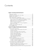 4
4 -
 5
5 -
 6
6 -
 7
7 -
8
-
9
-
10
-
11
-
12
-
13
-
14
-
15
-
16
-
17
-
18
-
19
-
20
-
21
-
22
-
23
-
24
-
25
-
26
-
27
-
28
-
29
-
30
-
31
-
32
-
33
-
34
-
35
-
36
-
37
-
38
-
39
-
40
-
41
-
42
-
43
-
44
-
45
-
46
-
47
-
48
-
49
-
50
-
51
-
52
-
53
-
54
-
55
-
56
-
57
-
58
-
59
-
60
-
61
-
62
-
63
-
64
-
65
-
66
-
67
-
68
-
69
-
70
-
71
-
72
-
73
-
74
-
75
-
76
-
77
-
78
-
79
-
80
-
81
-
82
-
83
-
84
-
85
-
86
-
87
-
88
-
89
-
90
-
91
-
92
-
93
-
94
-
95
-
96
-
97
-
98
-
99
-
100
-
101
-
102
-
103
-
104
-
105
-
106
-
107
-
108
-
109
-
110
-
111
-
112
-
113
-
114
-
115
-
116
-
117
-
118
-
119
-
120
-
121
-
122
-
123
-
124
-
125
-
126
-
127
-
128
-
129
-
130
-
131
-
132
-
133
-
134
-
135
-
136
-
137
-
138
-
139
-
140
-
141
-
142
-
143
-
144
-
145
-
146
-
147
-
148
-
149
-
150
-
151
-
152
-
153
-
154
-
155
-
156
-
157
-
158
-
159
-
160
-
161
-
162
-
163
-
164
-
165
-
166
-
167
-
168
-
169
-
170
-
171
-
172
-
173
-
174
-
175
-
176
-
177
-
178
-
179
-
180
-
181
-
182
-
183
-
184
-
185
-
186
-
187
-
188
-
189
-
190
-
191
-
192
-
193
-
194
-
195
-
196
-
197
-
198
-
199
-
200
-
201
-
202
-
203
-
204
-
205
-
206
-
207
-
208
-
209
-
210
-
211
-
212
-
213
-
214
-
215
-
216
-
217
-
218
-
219
-
220
-
221
-
222
-
223
-
224
-
225
-
226
-
227
-
228
-
229
-
230
-
231
-
232
-
233
-
234
-
235
-
236
-
237
-
238
-
239
-
240
-
241
-
242
-
243
-
244
-
245
-
246
-
247
-
248
-
249
-
250
-
251
-
252
-
253
-
254
-
255
-
256
-
257
-
258
-
259
-
260
-
261
-
262
-
263
-
264
-
265
-
266
-
267
-
268
-
269
-
270
-
271
-
272
-
273
-
274
-
275
-
276
-
277
-
278
-
279
-
280
-
281
-
282
-
283
-
284
-
285
-
286
-
287
-
288
-
289
-
290
-
291
-
292
-
293
-
294
-
295
-
296
-
297
-
298
-
299
-
300
-
301
-
302
-
303
-
304
-
305
-
306
-
307
-
308
-
309
-
310
-
311
-
312
-
313
-
314
-
315
-
316
-
317
-
318
-
319
-
320
-
321
-
322
-
323
-
324
-
325
-
326
-
327
-
328
-
329
-
330
-
331
-
332
-
333
-
334
-
335
-
336
-
337
-
338
-
339
-
340
-
341
-
342
-
343
-
344
-
345
-
346
-
347
-
348
-
349
-
350
-
351
-
352
-
353
-
354
-
355
-
356
-
357
-
358
-
359
-
360
-
361
-
362
-
363
-
364
-
365
-
366
-
367
-
368
-
369
-
370
-
371
-
372
-
373
-
374
-
375
-
376
-
377
-
378
-
379
-
380
-
381
-
382
-
383
-
384
-
385
-
386
-
387
-
388
-
389
-
390
-
391
-
392
-
393
-
394
-
395
-
396
-
397
-
398
-
399
-
400
-
401
-
402
-
403
-
404
-
405
-
406
-
407
-
408
-
409
-
410
-
411
-
412
-
413
-
414
-
415
-
416
-
417
-
418
-
419
-
420
-
421
-
422
-
423
-
424
-
425
-
426
-
427
-
428
-
429
-
430
-
431
-
432
-
433
-
434
-
435
-
436
-
437
-
438
-
439
-
440
-
441
-
442
-
443
-
444
-
445
-
446
-
447
-
448
-
449
-
450
-
451
-
452
-
453
-
454
-
455
-
456
-
457
-
458
-
459
-
460
-
461
-
462
-
463
-
464
-
465
-
466
-
467
-
468
-
469
-
470
-
471
-
472
-
473
-
474
-
475
-
476
-
477
-
478
-
479
-
480
-
481
-
482
-
483
-
484
-
485
-
486
-
487
-
488
-
489
-
490
-
491
-
492
-
493
-
494
-
495
-
496
-
497
-
498
-
499
-
500
-
501
-
502
-
503
-
504
-
505
-
506
-
507
-
508
-
509
-
510
-
511
-
512
-
513
-
514
-
515
-
516
-
517
-
518
-
519
-
520
-
521
-
522
-
523
-
524
-
525
-
526
-
527
-
528
-
529
-
530
-
531
-
532
-
533
-
534
-
535
-
536
-
537
-
538
-
539
-
540
-
541
-
542
-
543
-
544
-
545
-
546
-
547
-
548
-
549
-
550
-
551
-
552
-
553
-
554
-
555
-
556
-
557
-
558
-
559
-
560
-
561
-
562
-
563
-
564
-
565
-
566
-
567
-
568
-
569
-
570
-
571
-
572
-
573
-
574
-
575
-
576
-
577
-
578
-
579
-
580
-
581
-
582
-
583
-
584
-
585
-
586
-
587
-
588
-
589
-
590
-
591
-
592
-
593
-
594
-
595
-
596
-
597
-
598
-
599
-
600
-
601
-
602
-
603
-
604
-
605
-
606
-
607
-
608
-
609
-
610
-
611
-
612
-
613
-
614
-
615
-
616
-
617
-
618
-
619
-
620
-
621
-
622
-
623
-
624
-
625
-
626
-
627
-
628
-
629
-
630
-
631
-
632
-
633
-
634
-
635
-
636
-
637
-
638
-
639
-
640
-
641
-
642
-
643
-
644
-
645
-
646
-
647
-
648
-
649
-
650
-
651
-
652
-
653
-
654
-
655
-
656
-
657
-
658
-
659
-
660
-
661
-
662
-
663
-
664
-
665
-
666
-
667
-
668
-
669
-
670
-
671
-
672
-
673
-
674
-
675
-
676
-
677
-
678
-
679
-
680
-
681
-
682
-
683
-
684
-
685
-
686
-
687
-
688
-
689
-
690
-
691
-
692
-
693
-
694
-
695
-
696
-
697
-
698
-
699
-
700
-
701
-
702
-
703
-
704
-
705
-
706
-
707
-
708
-
709
-
710
-
711
-
712
-
713
-
714
-
715
-
716
-
717
-
718
-
719
-
720
-
721
-
722
-
723
-
724
-
725
-
726
-
727
-
728
-
729
-
730
-
731
-
732
-
733
-
734
-
735
-
736
-
737
-
738
-
739
-
740
-
741
-
742
-
743
-
744
-
745
-
746
-
747
-
748
-
749
-
750
-
751
-
752
-
753
-
754
-
755
-
756
-
757
-
758
-
759
-
760
-
761
-
762
-
763
-
764
-
765
-
766
-
767
-
768
-
769
-
770
-
771
-
772
-
773
-
774
-
775
-
776
-
777
-
778
-
779
-
780
-
781
-
782
-
783
-
784
-
785
-
786
-
787
-
788
-
789
-
790
-
791
-
792
-
793
-
794
-
795
-
796
-
797
-
798
-
799
-
800
-
801
-
802
-
803
-
804
-
805
-
806
-
807
-
808
-
809
-
810
-
811
-
812
-
813
-
814
-
815
-
816
-
817
-
818
-
819
-
820
-
821
-
822
-
823
-
824
-
825
-
826
 |
 |

Main User Manual
AV Line of Fully Managed Switches
M4250 Series
Firmware version 13.0.0 and later versions
NETGEAR, Inc.
350 E. Plumeria Drive
February 2023
San Jose, CA 95134, USA
202-12091-05