HP StorageWorks 8/80 HP StorageWorks Fabric OS 6.2 administrator guide (5697-0 - Page 350
Virtual Fabric considerations for Traffic Isolation Routing
 |
View all HP StorageWorks 8/80 manuals
Add to My Manuals
Save this manual to your list of manuals |
Page 350 highlights
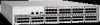
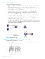
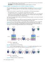
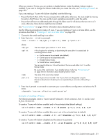
• Use care if defining TI zones with ports that are shared across Admin Domains because of the limitation that a given port can appear in only one TI zone. Best practice: Do not use ports that are shared across Admin Domains in a TI zone. Virtual Fabric considerations for Traffic Isolation Routing This section describes how TI zones work with Virtual Fabrics. See Chapter 6, "Managing virtual fabrics" on page 173 for information about the Virtual Fabrics feature, including Logical Switches and Logical Fabrics. TI zones can be created in a Logical Fabric like in regular fabrics, with the following exceptions: • The disable failover option is not supported in Logical Fabrics that use XISLs. • To create a TI zone for a Logical Fabric that uses XISLs, you must create two TI zones: one in the Logical Fabric and one in the base fabric. The combination of TI zones in the base fabric and Logical Fabric sets the path through the base fabric for Logical Switches. The TI zone in the Logical Fabric includes the extended XISL (XISL) port numbers, as well as the F_Ports and ISLs in the Logical Fabric. The TI zone in the base fabric reserves XISLs for a particular Logical Fabric. The base fabric TI zone should also include ISLs that belong to Logical Switches participating in the Logical Fabric. Figure 50 shows an initiator and target in a Logical Fabric (FID1). The dotted line indicates a dedicated path between initiator and target. The dedicated path passes through the base fabric over an XISL. (Figure 50 shows only physical ISLs, not logical ISLs.) To create the TI zones for this dedicated path, you must create a TI zone in the Logical Fabric (FID1) and one in the base fabric. Host Domain 8 Domain 9 Target 8 1 2 9 5 6 Chassis 1 3 4 LS3, FID1 Domain 3 LS4, FID3 Domain 4 10 Base switch Domain 1 11 XISL XISL Domain 7 12 14 13 15 XISL XISL 8 7 LS1, FID1 Domain 5 LS2, FID3 16 Domain 6 Base switch 17 Domain 2 Chassis 2 = Dedicated Path = Ports in the TI zones Figure 50 Dedicated path with Virtual Fabrics Figure 51 shows a logical representation of FID1 in Figure 50. To create the dedicated path, you must create and activate a TI zone in FID1 that includes the circled ports shown in Figure 51. Host Domain 8 Domain 3 Domain 5 2 4 11 17 7 8 1 3 10 16 8 Domain 9 6 9 5 Target = Dedicated Path = Ports in the TI zones Figure 51 Creating a TI zone in a Logical Fabric 348 Optimizing fabric behavior
-
 1
1 -
2
-
3
-
4
-
5
-
6
-
7
-
8
-
9
-
10
-
11
-
12
-
13
-
14
-
15
-
16
-
17
-
18
-
19
-
20
-
21
-
22
-
23
-
24
-
25
-
26
-
27
-
28
-
29
-
30
-
31
-
32
-
33
-
34
-
35
-
36
-
37
-
38
-
39
-
40
-
41
-
42
-
43
-
44
-
45
-
46
-
47
-
48
-
49
-
50
-
51
-
52
-
53
-
54
-
55
-
56
-
57
-
58
-
59
-
60
-
61
-
62
-
63
-
64
-
65
-
66
-
67
-
68
-
69
-
70
-
71
-
72
-
73
-
74
-
75
-
76
-
77
-
78
-
79
-
80
-
81
-
82
-
83
-
84
-
85
-
86
-
87
-
88
-
89
-
90
-
91
-
92
-
93
-
94
-
95
-
96
-
97
-
98
-
99
-
100
-
101
-
102
-
103
-
104
-
105
-
106
-
107
-
108
-
109
-
110
-
111
-
112
-
113
-
114
-
115
-
116
-
117
-
118
-
119
-
120
-
121
-
122
-
123
-
124
-
125
-
126
-
127
-
128
-
129
-
130
-
131
-
132
-
133
-
134
-
135
-
136
-
137
-
138
-
139
-
140
-
141
-
142
-
143
-
144
-
145
-
146
-
147
-
148
-
149
-
150
-
151
-
152
-
153
-
154
-
155
-
156
-
157
-
158
-
159
-
160
-
161
-
162
-
163
-
164
-
165
-
166
-
167
-
168
-
169
-
170
-
171
-
172
-
173
-
174
-
175
-
176
-
177
-
178
-
179
-
180
-
181
-
182
-
183
-
184
-
185
-
186
-
187
-
188
-
189
-
190
-
191
-
192
-
193
-
194
-
195
-
196
-
197
-
198
-
199
-
200
-
201
-
202
-
203
-
204
-
205
-
206
-
207
-
208
-
209
-
210
-
211
-
212
-
213
-
214
-
215
-
216
-
217
-
218
-
219
-
220
-
221
-
222
-
223
-
224
-
225
-
226
-
227
-
228
-
229
-
230
-
231
-
232
-
233
-
234
-
235
-
236
-
237
-
238
-
239
-
240
-
241
-
242
-
243
-
244
-
245
-
246
-
247
-
248
-
249
-
250
-
251
-
252
-
253
-
254
-
255
-
256
-
257
-
258
-
259
-
260
-
261
-
262
-
263
-
264
-
265
-
266
-
267
-
268
-
269
-
270
-
271
-
272
-
273
-
274
-
275
-
276
-
277
-
278
-
279
-
280
-
281
-
282
-
283
-
284
-
285
-
286
-
287
-
288
-
289
-
290
-
291
-
292
-
293
-
294
-
295
-
296
-
297
-
298
-
299
-
300
-
301
-
302
-
303
-
304
-
305
-
306
-
307
-
308
-
309
-
310
-
311
-
312
-
313
-
314
-
315
-
316
-
317
-
318
-
319
-
320
-
321
-
322
-
323
-
324
-
325
-
326
-
327
-
328
-
329
-
330
-
331
-
332
-
333
-
334
-
335
-
336
-
337
-
338
-
339
-
340
-
341
-
342
-
343
-
344
-
 345
345 -
 346
346 -
 347
347 -
 348
348 -
 349
349 -
 350
350 -
 351
351 -
 352
352 -
 353
353 -
 354
354 -
 355
355 -
356
-
357
-
358
-
359
-
360
-
361
-
362
-
363
-
364
-
365
-
366
-
367
-
368
-
369
-
370
-
371
-
372
-
373
-
374
-
375
-
376
-
377
-
378
-
379
-
380
-
381
-
382
-
383
-
384
-
385
-
386
-
387
-
388
-
389
-
390
-
391
-
392
-
393
-
394
-
395
-
396
-
397
-
398
-
399
-
400
-
401
-
402
-
403
-
404
-
405
-
406
-
407
-
408
-
409
-
410
-
411
-
412
-
413
-
414
-
415
-
416
-
417
-
418
-
419
-
420
-
421
-
422
-
423
-
424
-
425
-
426
-
427
-
428
-
429
-
430
-
431
-
432
-
433
-
434
-
435
-
436
-
437
-
438
-
439
-
440
-
441
-
442
-
443
-
444
-
445
-
446
-
447
-
448
-
449
-
450
-
451
-
452
-
453
-
454
-
455
-
456
-
457
-
458
-
459
-
460
-
461
-
462
-
463
-
464
-
465
-
466
-
467
-
468
-
469
-
470
-
471
-
472
-
473
-
474
-
475
-
476
-
477
-
478
-
479
-
480
-
481
-
482
-
483
-
484
-
485
-
486
-
487
-
488
-
489
-
490
-
491
-
492
-
493
-
494
-
495
-
496
-
497
-
498
-
499
-
500
-
501
-
502
-
503
-
504
-
505
-
506
-
507
-
508
-
509
-
510
-
511
-
512
-
513
-
514
-
515
-
516
-
517
-
518
-
519
-
520
-
521
-
522
-
523
-
524
-
525
-
526
-
527
-
528
-
529
-
530
-
531
-
532
-
533
-
534
-
535
-
536
-
537
-
538
-
539
-
540
-
541
-
542
-
543
-
544
-
545
-
546
-
547
-
548
-
549
-
550
-
551
-
552
-
553
-
554
-
555
-
556
-
557
-
558
-
559
-
560
-
561
-
562
-
563
-
564
-
565
-
566
-
567
-
568
-
569
-
570
-
571
-
572
-
573
-
574
-
575
-
576
 |
 |